Plural compressors

a compressor and plug-in technology, applied in the direction of liquid fuel engines, positive displacement liquid engines, lighting and heating apparatus, etc., can solve the problems of variable capacity systems that are relatively complex, variable speed compressors that require expensive controls, and the efficiency of variable speed compressors stated is not optimal, so as to reduce the overall cost and the overall size of the system, the effect of maximizing the compactness of the system

Active Publication Date: 2007-04-10
COPELAND LP
View PDF4 Cites 33 Cited by
  • Summary
  • Abstract
  • Description
  • Claims
  • Application Information

AI Technical Summary

Benefits of technology

[0004]Additional designs for the multi-compressor systems have included the incorporation of a plurality of standard motor compressor units in a common single compressor shell. The common shell maximizes the compactness of the system and it provides a common oil sump for equal oil distribution, a common suction gas inlet and a common discharge gas outlet. These single shell multi-compressor systems have proved to

Problems solved by technology

These variable capacity systems tend to be relatively complex and the efficiency of the compressor in an unloaded stated is not optimum.
Variable speed compressors have also been used, but these variable speed compressors require expensive controls.
The efficiency of the speed control, as well as the efficiency of

Method used


Image

  • Plural compressors
  • Plural compressors
  • Plural compressors

Examples


Embodiment Construction

[0024]The following description of the preferred embodiment(s) is merely exemplary in nature and is in no way intended to limit the invention, its application, or uses.

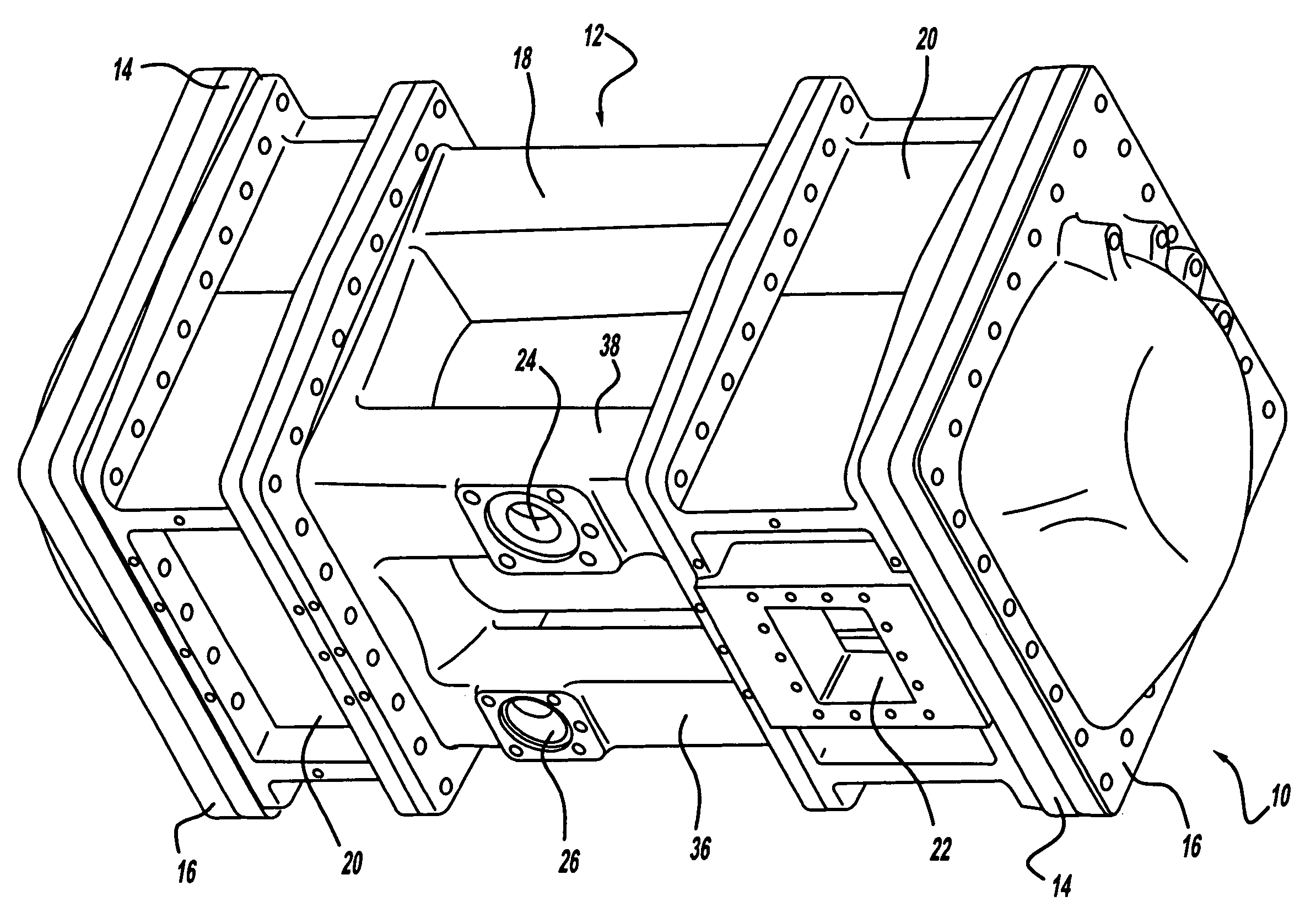
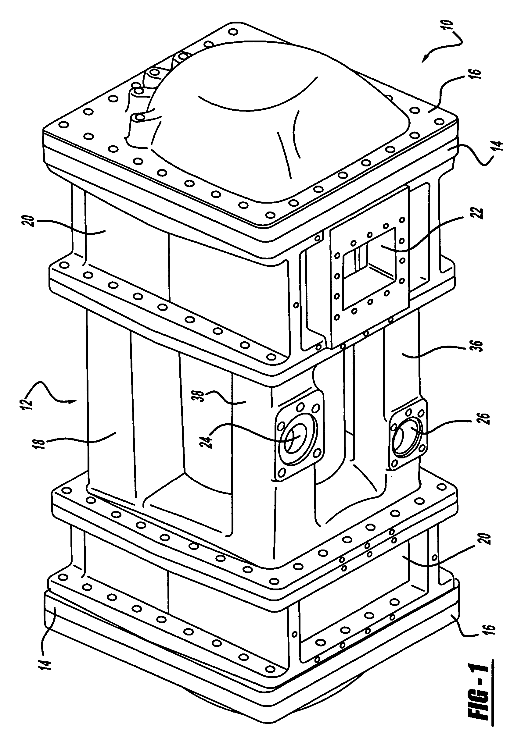
[0025]There is shown in FIG. 1 a multi-compressor compression system in accordance with the present invention which is designated generally by the reference numeral 10. Compression system 10 comprises a multi-piece hermetic shell assembly 12 having bolted at each end thereof a partition plate assembly 14 and an end cap 16.

[0026]Shell assembly 12 comprises a central shell 18 and a pair of intermediate shells 20, with each intermediate shell 20 being located at opposite ends of central shell 18. Each intermediate shell 20 is bolted to central shell 18 as shown in FIG. 1. One intermediate shell 20 defines an electrical connection access 22 for providing electrical and diagnostic connection to the motor within shell assembly 12. Central shell 18 is provided with a single suction inlet fitting 24 and a single discharge fit...


PUM


Abstract

A compressor system includes a pair of compressors located in a common shell. A common drive shaft drives both compressors and the drive shaft is powered by a single motor. One or both of the compressors can be equipped with a pulse width modulated capacity control system and a vapor injection system. When one compressor is equipped with these systems, the capacity can be varied between 50% and 110%. When both compressors are equipped with these systems, the capacity can be varied between 0% and 120%.

Description

FIELD OF THE INVENTION[0001]The present invention relates to plural compressors disposed within a single shell. More particularly, the present invention relates to plural compressors disposed within a single shell where two compressors, located at opposite ends of a motor, are both driven by the motor.BACKGROUND AND SUMMARY OF THE INVENTION[0002]Due to energy costs and conservation, there is a demand for refrigerant motor-compressor systems which have an output which can be varied in accordance with demand. To satisfy this demand, a large number of systems have been developed. One such system involves the unloading of one or more cylinders in a multi-cylinder compressor or the varying of re-expansion volume for the purpose of varying the output of the compressor system. These variable capacity systems tend to be relatively complex and the efficiency of the compressor in an unloaded stated is not optimum. Variable speed compressors have also been used, but these variable speed compre...

Claims


Application Information

Patent Timeline
IPC IPC(8): F04B17/03F01C1/02F01C1/063F01C21/10F04C18/02F04C23/00F04C29/00F04C29/02F04C29/04
CPCF01C21/10F04C18/0215F04C23/001F04C29/0085F04C29/042F04C23/008F04C29/023F25B1/04F25B2400/13F25B2600/0253F04C18/02
Inventor WIERTZ, GUIDOISERENTANTE, ROBERTDOUTREPONT, DIDIERDOBRESCU, JOHANNPIRENNE, FRANCISANDERSON, GARYERNST, PHILIPPEVERHOFF, CLYDEPOYSAT, PIERRE
Owner COPELAND LP
Why Eureka
Try Eureka