Ventilation system, air blowing and extraction circuits of such a system, as well as an aircraft avionics bay

a technology of air blowing and air circuit, which is applied in the direction of electrical apparatus construction details, cooling/ventilation/heating modifications, aircraft accessories, etc., can solve the problems of circuit duplicates, circuits that pose problems in installation, and the integration of electric/electronic materials is also problemati

Active Publication Date: 2015-12-22
AIRBUS OPERATIONS (SAS)
View PDF12 Cites 1 Cited by
  • Summary
  • Abstract
  • Description
  • Claims
  • Application Information

AI Technical Summary

Benefits of technology

[0009]The embodiments of the present invention overcome at least some of the drawbacks linked to such installation constraints with a multifunctional approach for the operational components of the avionics bay and of the structural parts of a floor, substantially in their initial volume. Moreover, the embodiments of the present provide gains in terms of mass and cost by reducing the number of parts and making an integration of the system.
[0021]a sealing resin is deposited on each strut assembly so as to increase sealing.
[0023]An embodiment of the invention also relates to an extraction circuit of an avionics bay integrated into an aircraft, comprising at least one cabinet, in particular an aircraft cockpit. Such particular ventilation system extraction circuit, as defined above, comprises transmission conducts integrated into the cabinets and dedicated to the inter-cabinets air transmission so as to provide an overall configuration of a maximized compactness.
[0030]An embodiment of the invention also relates to an avionics bay comprising cabinets and integrating an air transmission circuit which is adapted to serve as an extraction circuit and a blowing circuit for the above mentioned ventilation system. Such transmission circuit comprises air transmission conducts integrated into the cabinets and dedicated to the inter-cabinets air transmission so as to provide an overall configuration of a maximized compactness. The cabinets are then arranged the closest to each other so that the inter-cabinets conducts and sleeves present a minimal congestion.

Problems solved by technology

Such circuits are duplicated for safety reasons.
Such circuits pose problems in terms of installation due to the complexity of their shape because of the small volume available.
Moreover, in the cargo bay, the integration of the electric / electronic material is also problematic because this area is not secured.
However, the problem of the congestion is then posed abruptly, since such secured front area, in particular the cockpit, is already well filled with the whole equipment and apparatus thereof.
Nevertheless, these means present installation constraints being difficult to manage due to the complexity and the volume thereof, as well as through their fragile construction in a light and thin material (in general a composite material).

Method used


Image

  • Ventilation system, air blowing and extraction circuits of such a system, as well as an aircraft avionics bay
  • Ventilation system, air blowing and extraction circuits of such a system, as well as an aircraft avionics bay
  • Ventilation system, air blowing and extraction circuits of such a system, as well as an aircraft avionics bay

Examples


Embodiment Construction

[0038]In the present description, the terms “forward”, “backward”, “front”, “rear”“under”, “upper”, “lower”, “lateral”, “transversal”, “internal”, “external”, “vertical”, “horizontal’, and the derivatives or equivalents thereof relate to relative positionings for elements in a standard configuration of an airplane lying on the ground and with respect to a longitudinal plane of symmetry being vertical in this configuration.

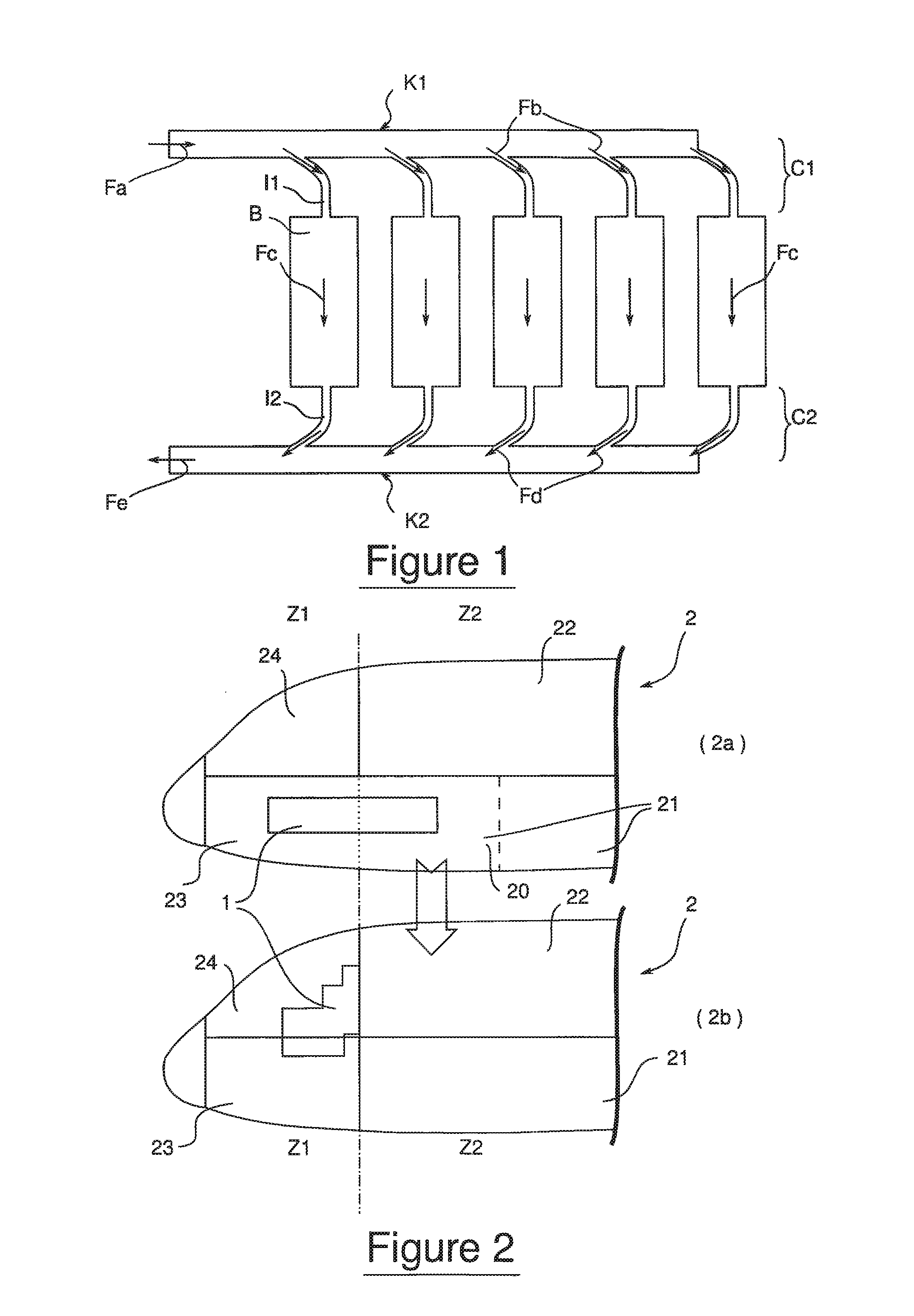
[0039]Referring to the principle schema of FIG. 2, the installation of the avionics bay 1 in an airplane 2 is conventionally distributed (schema 2a) between a part 20 of the cargo area 21—located under the passenger cabin 22 in a non secured area Z2—and the front bay 23 located under the cockpit 24 in a secured area Z1. According to an embodiment of the invention (schema 2b), the avionics bay 1 is partially displaced so as to come totally in the secured area Z1 forward of the airplane 2 through a distribution of the bay between the front bay 23 and the cockpit 24.

[...


PUM


Abstract

A ventilation system for an avionics bay has two strut assemblies for stiffening the floor of the cockpit, each strut assembly being arranged symmetrically regarding to the central plane of the aircraft, and means of distribution of the blowing air in the cabinets of the bay from the strut assemblies. The extraction circuit includes exhaust ducts integrated in the cabinets and couples together by tight inter-cabinets junctions in an overall configuration of maximized compactness.

Description

FIELD OF THE INVENTION[0001]The present invention relates to ventilation systems of an avionics bay of an aircraft, in particular to the blowing and extraction air circuits for such system.[0002]The invention generally applies to aircrafts provided with an avionics bay grouping together electric and electronic material as cabinets integrating electric cores, calculators and / or other electronic equipment (converters, etc.) and / or modules pertaining to the electric / electronic equipment, such as power modules, batteries, inertial units, etc. Electric harnesses being coupled to such bay allow this material to be connected to the functional or operational devices being concerned via the on-board network.[0003]In operation, such material dissipates heat. The field of the invention relates to the continuous cooling of such material through transfer of the heat being dissipated. In the present disclosure, the expression “avionics bay” is not restrained to airplanes, but can apply to any typ...

Claims


Application Information

Patent Timeline
Patent Type & Authority Patents(United States)
IPC IPC(8): B64C1/00H05K7/20B64D13/00B64C1/18B64D13/06
CPCB64C1/18H05K7/20554B64D13/00B64D2013/0614
Inventor GUERING, BERNARDDURAND, YVES
Owner AIRBUS OPERATIONS (SAS)
Why Eureka
Try Eureka