
Vacuum cleaner

a vacuum cleaner and vacuum cleaner technology, applied in the field of vacuum cleaners, can solve the problems of inconvenient storage, moving or carrying the vacuum cleaner, the connecting components of the entire vacuum cleaner are difficult to gather, and cannot be stored into the main body portion so as to ensure the performance of the vacuum cleaner, reduce the space occupied by the suction pipe unit, and minimize the distance between the battery

Pending Publication Date: 2022-04-21
POSITEC POWER TOOLS (SUZHOU) CO LTD
View PDF0 Cites 1 Cited by
  • Summary
  • Abstract
  • Description
  • Claims
  • Application Information

AI Technical Summary

Benefits of technology

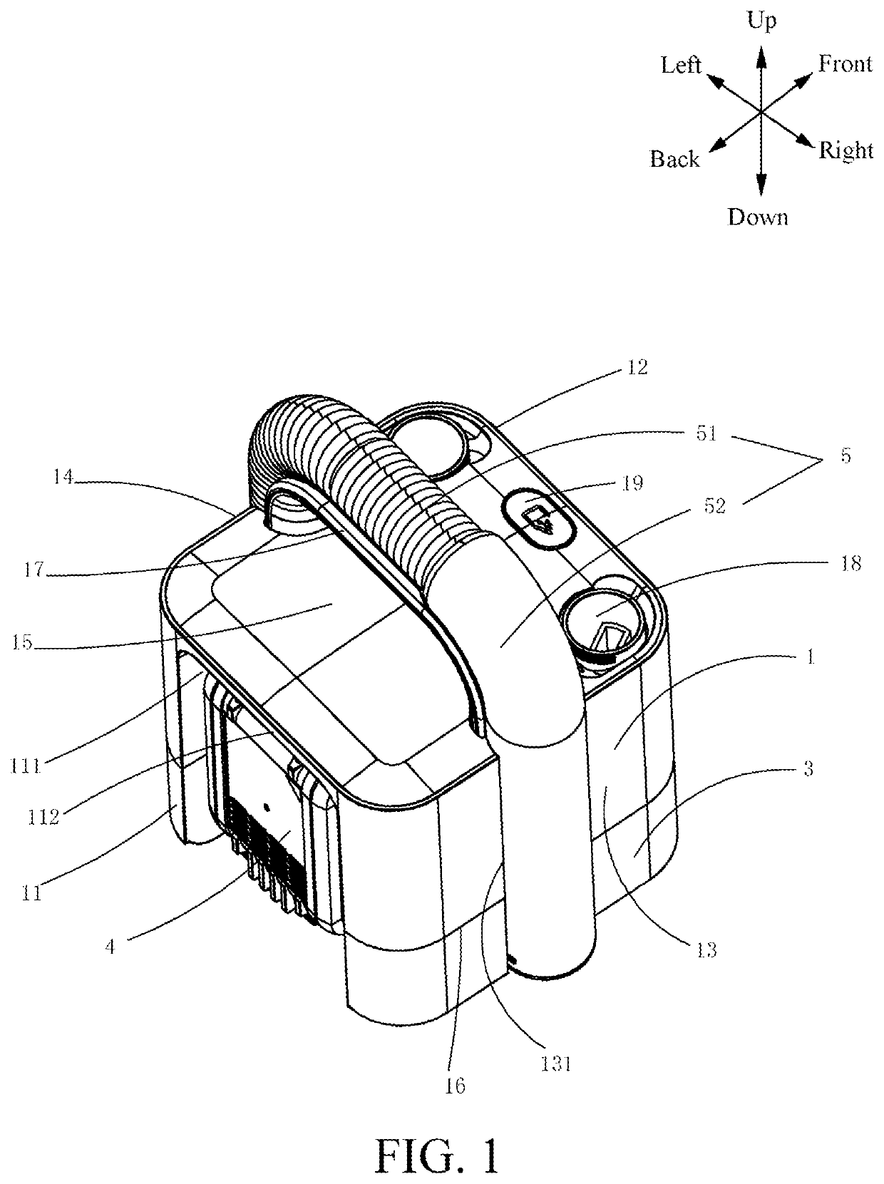
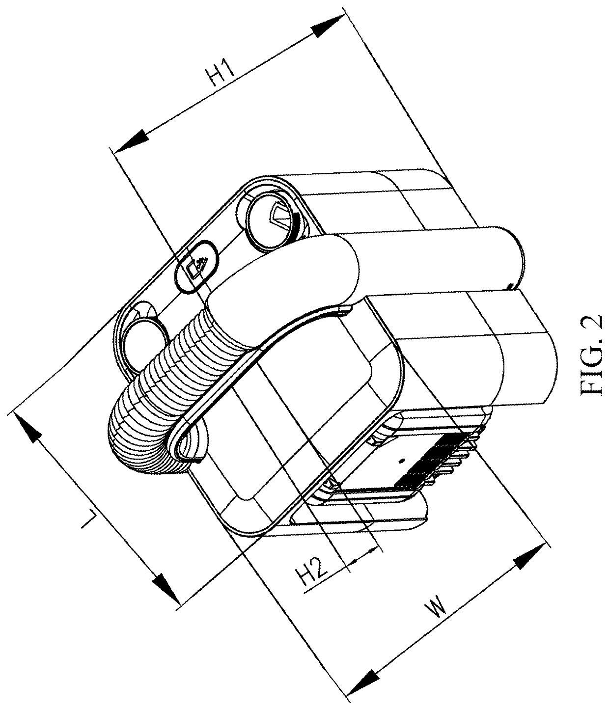
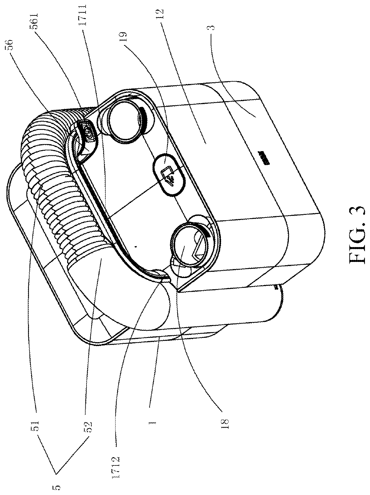
The present invention is about a vacuum cleaner that can be easily stored when not in use. The motor unit and dust cup are placed in a way that their axes are parallel to each other and run along the motor unit's axial direction, making them more compact. When stored, the suction pipe unit extends from one side of the dust cup to the handle, reducing space occupied. The battery is placed on one side of the housing, minimizing the distance between it and the motor unit and dust cup, making the vacuum cleaner more compact. The structural design allows for the use of a compact motor unit while ensuring sufficient power output.

Problems solved by technology

Most of the existing vacuum cleaners are in a form of a handheld, bucket, or box vacuum cleaner incapable of storing accessories or hoses.
When a vacuum cleaner is in a storage state, none of the hoses, the accessories, and the like of the vacuum cleaner can be stored in the main body portion of the vacuum cleaner, to miniaturize the entire vacuum cleaner, resulting in inconvenience in storing, moving, or carrying the vacuum cleaner.
Consequently, connecting components of the entire vacuum cleaner are uneasy to gather together.
Secondarily, although hoses or accessories of most of the vacuum cleaners are detachably mounted, the hoses or accessories after disassembly still need to be carried additionally, and cannot be stored into the main body portion of the vacuum cleaner.

Method used


Image

  • Vacuum cleaner
  • Vacuum cleaner
  • Vacuum cleaner

Examples


Embodiment Construction

[0380]The present embodiments provide a vacuum cleaner, which is flexible to operate and has a long single cleaning time.

[0381]Exemplary implementations of the present invention are described below in detail with reference to the accompanying drawings. It should be understood that the detailed descriptions are merely used for teaching a person skilled in the art to implement the present embodiments, but are not used to exhaust all manners of the present embodiments and are not used for limiting the scope of the present embodiments.

[0382]It should be noted that, when a component is referred to as “being fixed to” another component, the component may be directly on the other component, or an intervening component may be present. When a component is considered to be “connected to” another component, the component may be directly connected to the another component, or an intervening component may also be present. In contrast, when a component is referred to as being “directly on” or “di...


PUM


Abstract

A vacuum cleaner, comprising: a housing; a motor unit provided in the housing and used for generating suction force; a dust cup provided on the housing and used for collecting sucked particles, the dust cup comprising a suction inlet; a battery for supplying power to the vacuum cleaner; a handle located on the housing; and a suction pipe unit having a storage state, wherein under the storage state, the suction pipe unit extends from the suction inlet on one side of the dust cup, across the handle, and to the other side of the dust cup along the length direction of the handle. The motor unit and the dust cup are located on the same straight line direction; the battery is provided on a side of the housing. The layout of the whole machine components of the present vacuum cleaner is optimized, and the performance of the vacuum cleaner is guaranteed under the premise of miniaturization.

Description

[0001]This application claims priority to Chinese Patent Application No. 201921031829.2, filed on Jul. 4, 2019, which is incorporated herein by reference in its entirety.BACKGROUNDTechnical Field[0002]The present embodiments belong to the field of cleaning technologies, and in particular, to a vacuum cleaner.Related Art[0003]Most of the existing vacuum cleaners are in a form of a handheld, bucket, or box vacuum cleaner incapable of storing accessories or hoses. When a vacuum cleaner is in a storage state, none of the hoses, the accessories, and the like of the vacuum cleaner can be stored in the main body portion of the vacuum cleaner, to miniaturize the entire vacuum cleaner, resulting in inconvenience in storing, moving, or carrying the vacuum cleaner. While a vacuum cleaner is miniaturized and performance is ensured, in most cases, hoses, accessories, and the like of the vacuum cleaner are all connected to the suction port of the vacuum cleaner. Consequently, connecting component...

Claims


Application Information

Patent Timeline
Patent Type & Authority Applications(United States)
IPC IPC(8): A47L9/00A47L5/36A47L9/22A47L9/14A47L9/28A47L9/24A47L9/32
CPCA47L9/0036A47L5/365A47L9/22A47L9/1409A47L9/2884A47L9/0045A47L9/0027A47L9/149A47L9/244A47L9/327A47L9/248A47L9/28A47L9/00A47L5/12A47L9/2868A47L7/00A47L9/24A47L9/0477A47L9/0072A47L5/26A47L9/242A47L7/0019A47L9/322A47L9/0693
Inventor DANG, YAZHOUJI, SHAOSHANWU, HONGBING
Owner POSITEC POWER TOOLS (SUZHOU) CO LTD
Learn More