
Method and system for design and modeling of transmission lines

Inactive Publication Date: 2008-07-31
GLOBALFOUNDRIES INC
View PDF2 Cites 2 Cited by
  • Summary
  • Abstract
  • Description
  • Claims
  • Application Information

AI Technical Summary

Benefits of technology

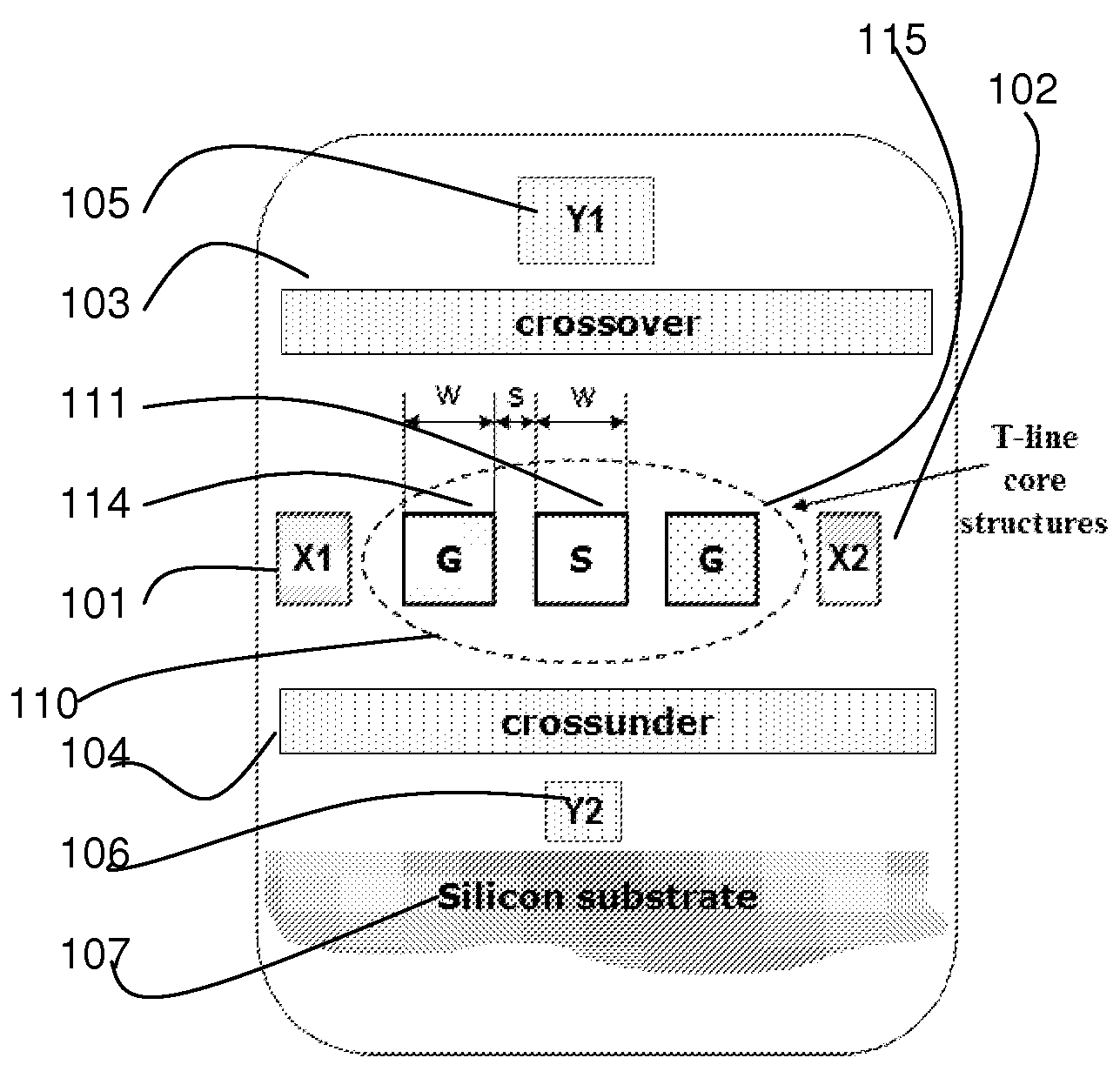
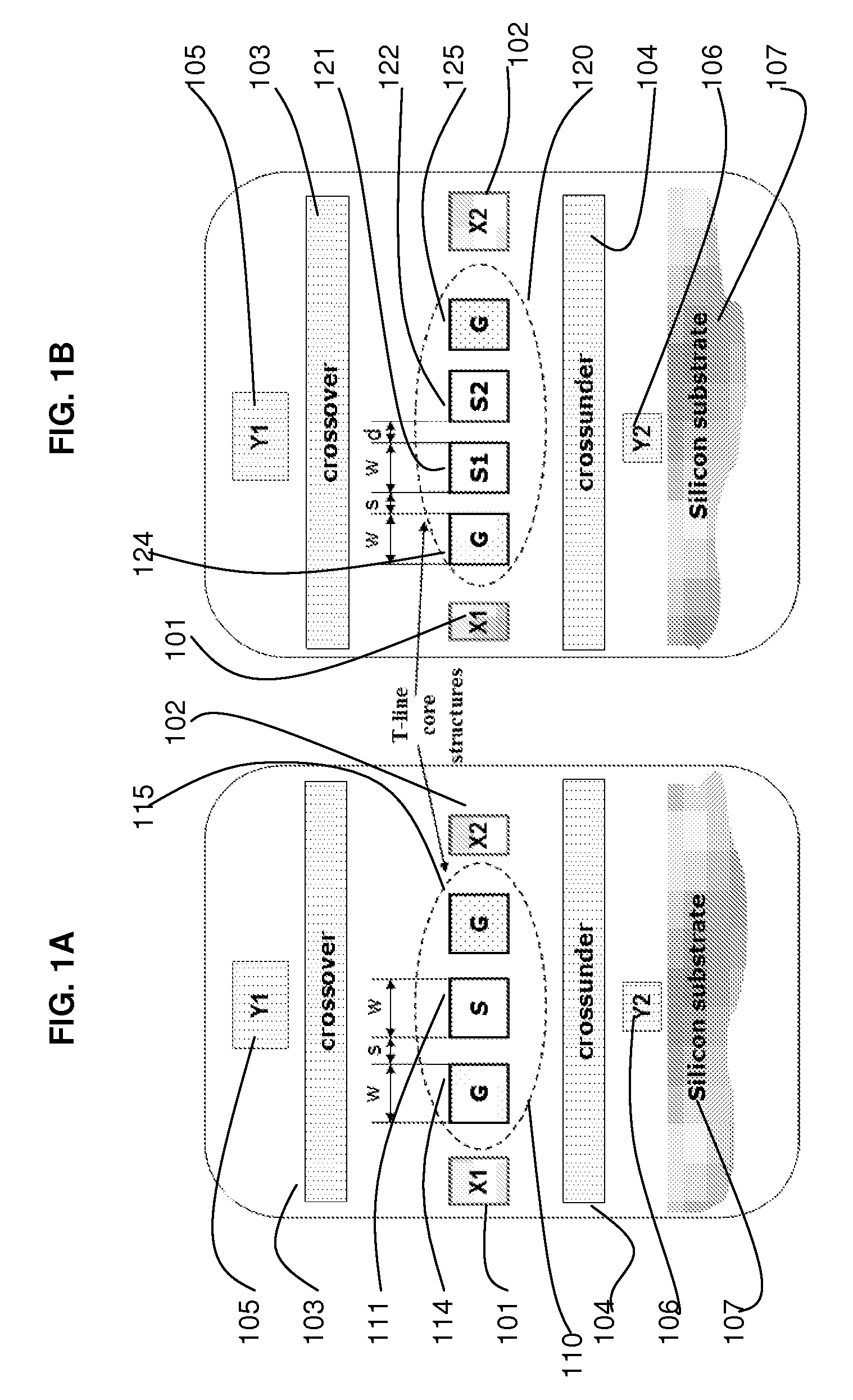
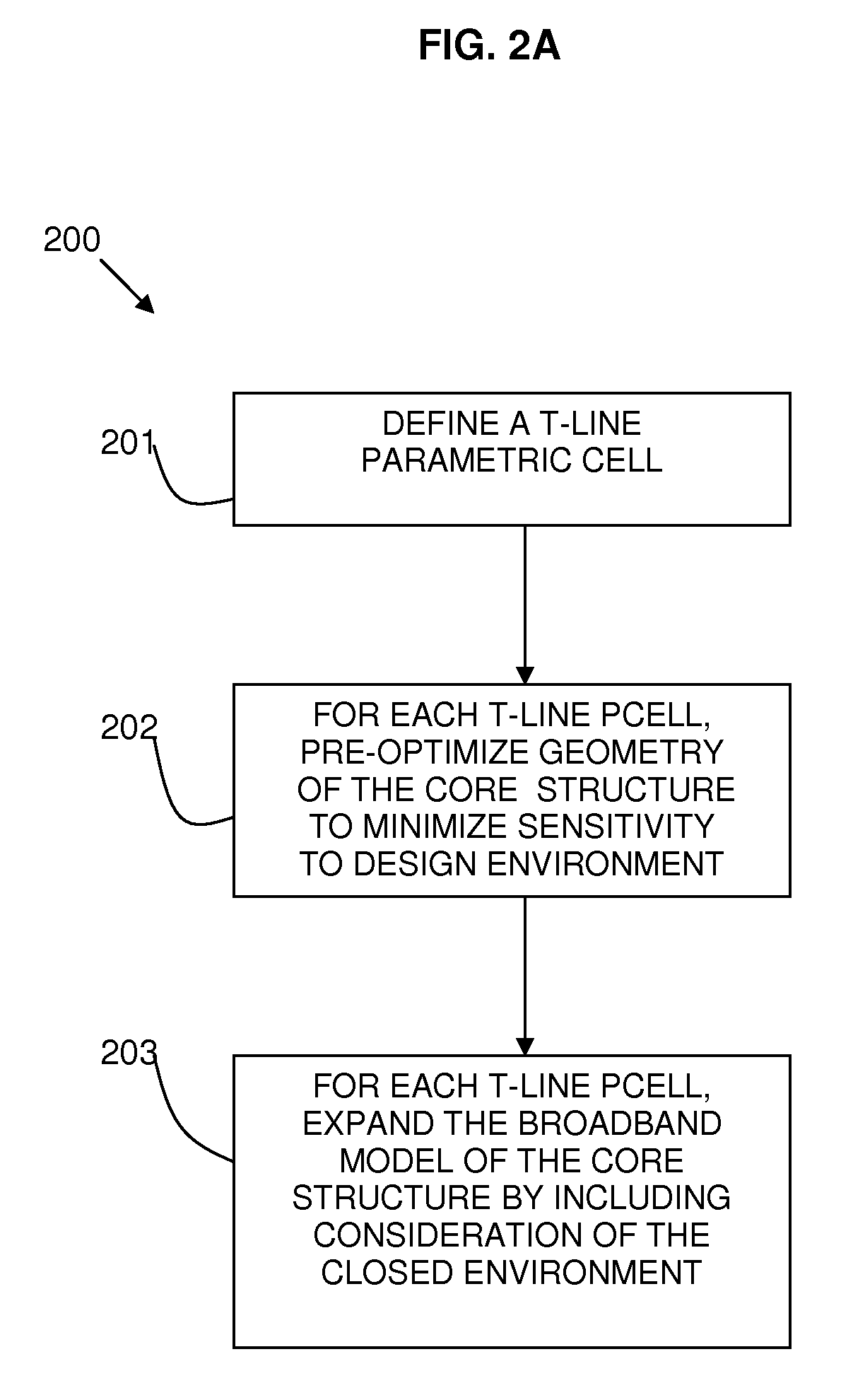
[0006]It is an aim of the present invention to design on-chip transmission lines (T-lines) so that they ensure the desired T-line performance in an actual VL

Problems solved by technology

In multi-GHz chip design domains, interconnects are becoming the limiting factor in the performance, energy dissipation, and signal integrity.
The demanding requirements from on-chip wiring pose a serious problem, both from the design and the modeling aspects.
The attempts to develop post-layout RCL extraction methods usually fail to correctly determine the wire inductances, due to the inability to determine the correct current return paths.
In addition, existing RC(L) extraction tools do not take into account several physical effects, such as substrate effects, which are expected to have a significant impact on the design performance.
As a result, the solution domain can be either redundant or insufficient, or both, which leads to errors that are almost impossible to track.

Method used


Image

  • Method and system for design and modeling of transmission lines
  • Method and system for design and modeling of transmission lines
  • Method and system for design and modeling of transmission lines

Examples


Embodiment Construction

[0039]In the following detailed description, numerous specific details are set forth in order to provide a thorough understanding of the invention. However, it will be understood by those skilled in the art that the present invention may be practiced without these specific details. In other instances, well-known methods, procedures, and components have not been described in detail so as not to obscure the present invention.

[0040]Interconnect-aware design and modeling methodology provides a comprehensive solution for on-chip wiring design and modeling. Further information is provided in references: Goren, D. et al., “An Interconnect-Aware Methodology for Analog and Mixed Signal Design, Based on High Bandwidth (Over 40 GHz) On-chip Transmission Line Approach” IEEE DATE'02 Conference, Paris March 2002, pp. 804-811 and Goren, D. et al., “On-chip Interconnect-Aware Design and Modeling Methodology, Based on High Bandwidth Transmission Line Devices”, IEEE DAC'03 Conference, CA, June 2003, ...


PUM


Abstract

A method and system for design and modeling of transmission lines are provided. The method includes providing a set of models of core structures (211) of transmission line cells and expanding each of the models of core structures (211) to include different neighboring elements. The parameter characteristics of the expanded core structures (214a-214c) are compared to determine a model having a minimal sufficiently closed neighborhood environment. A closed neighborhood environment complies with design rules to ensure desired transmission line behaviour in a real design environment. A model having a closed neighborhood environment can be used as a stand-alone model of the core structure describing the transmission line behaviour in the actual design environment.

Description

FIELD OF THE INVENTION[0001]This invention relates to the field of design and modeling of transmission lines. In particular, the invention relates to on-chip transmission line design and modeling in dense VLSI design environment.BACKGROUND OF THE INVENTION[0002]In multi-GHz chip design domains, interconnects are becoming the limiting factor in the performance, energy dissipation, and signal integrity. The demanding requirements from on-chip wiring pose a serious problem, both from the design and the modeling aspects.[0003]Previous solutions for considering on-chip interconnects have focused on analysis of given designs. These include RC(L) extraction methods and analysis tools based on field solvers.[0004]The attempts to develop post-layout RCL extraction methods usually fail to correctly determine the wire inductances, due to the inability to determine the correct current return paths. In addition, existing RC(L) extraction tools do not take into account several physical effects, s...

Claims


Application Information

Patent Timeline
IPC IPC(8): G06F17/50
CPCG06F17/5036G06F30/367
Inventor CARMON, ROIGORDIN, RACHELGOREN, DAVIDSHLAFMAN, SHLOMO
Owner GLOBALFOUNDRIES INC
Learn More