X-ray device

a technology of x-ray and x-ray tubes, which is applied in the direction of radiation control devices, instruments, applications, etc., can solve the problems of poor image quality and the achievement of the required positioning accuracy, and achieve the effect of maximizing the compactness of the construction uni

Active Publication Date: 2017-11-21
SIEMENS HEALTHCARE GMBH
View PDF18 Cites 2 Cited by
  • Summary
  • Abstract
  • Description
  • Claims
  • Application Information

AI Technical Summary

Benefits of technology

[0008]In accordance with the present teachings, a torque motor may be used as a drive motor instead of a conventional electric motor-gear unit. The torque motor includes a stator and a rotor. The stator is fixed in position relative to the C-bracket, and the rotor rotates relative to the stator with extremely high positioning accuracy. In accordance with the present teachings, the radiation detector is coupled to the rotor. A torque motor as a direct drive is distinguished by the absence of mechanical transmission elements (e.g., gearwheels or a gear). The output shaft (e.g., the rotor) is simultaneously the motor shaft, thereby resulting in very high torsional stiffness and freedom from backlash in the drive train. Freedom from backlash in the drive train is a precondition for highly precise movement and, therefore, high positioning accuracy. A torque motor may be used to achieve a positioning accuracy of 0.02 angular degrees or less with an x-ray device in accordance with the present teachings.
[0009]Due to the relatively large diameters of the rotor, a correspondingly high torque is produced. The high torque may be advantageous for positional accuracy and accurate, reproducible rotation of the detector.
[0012]Regardless of whether the radiation detector is arranged directly on the rotor, or the rotor and the radiation detector are coupled by an adapter, screw connections may be used for connection parts, thereby facilitating disassembly of the individual interconnected components for maintenance purposes.
[0015]To maximize the compactness of the constructional unit, a hollow-cylindrical, housing-type projection that the cylindrical torque motor is inserted into may be provided on the C-bracket. The torque motor may be within the bracket or accommodated within the cylindrical, housing-type projection. For example, the torque motor may be inserted to such an extent that the rotor may still be connected to the radiation detector, mounting plate, or adapter. The housing of the radiation detector may also have a hollow-cylindrical projection that fits at least partially around the outside of the projection of the C-bracket, thereby providing a closed unit.

Problems solved by technology

Although rotation of the detector may be effected with this kind of a drive, there may be problems in achieving the required positioning accuracy (e.g., detector rotation during a movement of the C-bracket).
As a result, image quality may be poorer as compared to images recorded with a stationary radiation detector.

Method used


Image

  • X-ray device
  • X-ray device
  • X-ray device

Examples


Embodiment Construction

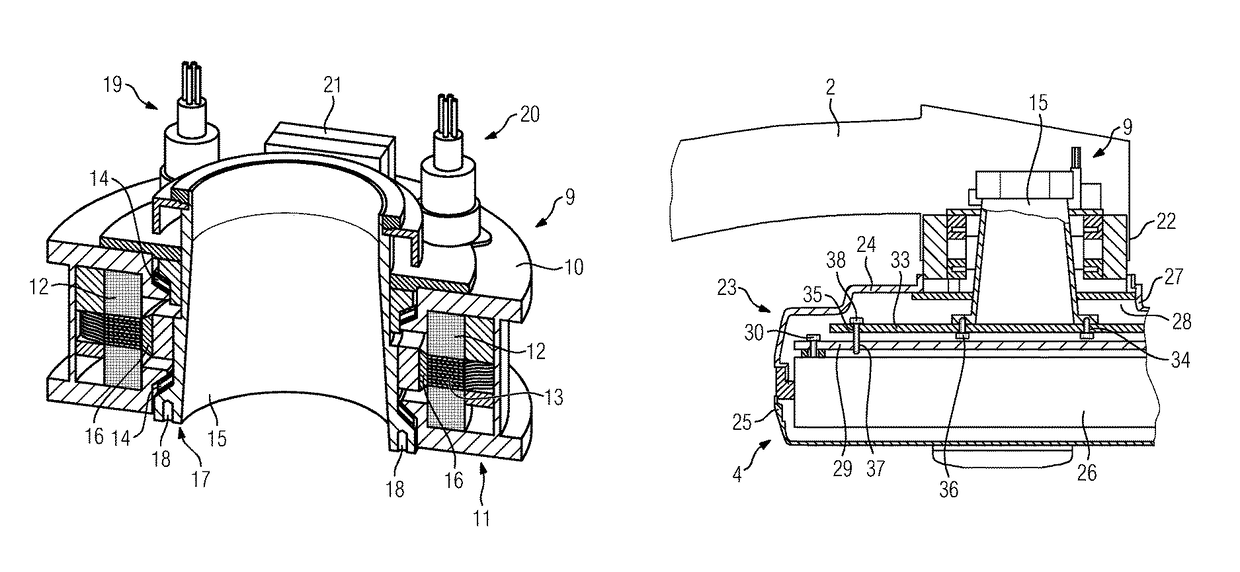
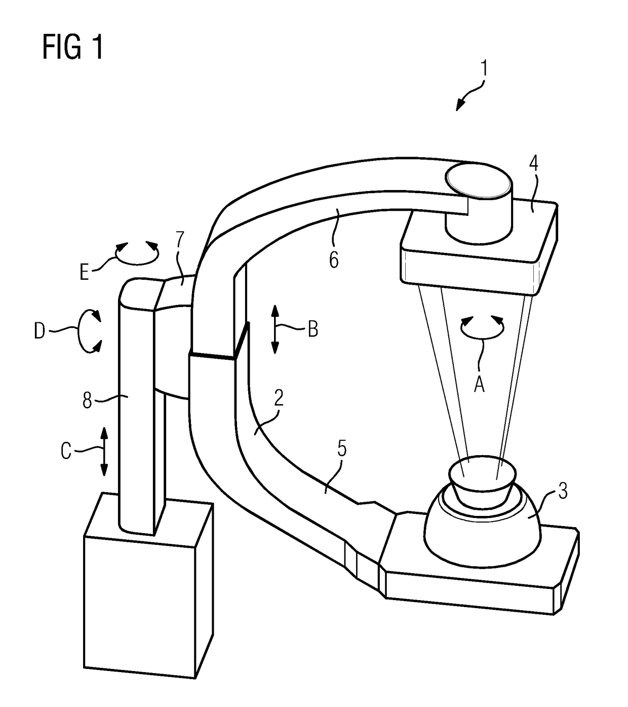
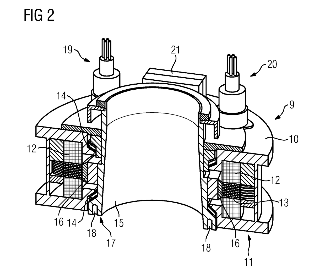
[0020]FIG. 1 shows an x-ray device 1 in accordance with the present teachings. The x-ray device 1 includes a C-bracket 2. A radiation source 3 (e.g., an x-ray radiation source) is arranged on one end of the C-bracket 2, and a radiation detector 4 (e.g., a flat-image detector including a radiation-sensitive pixel matrix) is arranged on the other end of the C-bracket 2. As further described below, the radiation detector 4 may be rotated about an axis of rotation perpendicular to the image-recording or matrix plane by a drive part (e.g., in the form of a torque motor), as indicated by the double arrow A.

[0021]In the illustrative embodiment shown in FIG. 1, the C-bracket 2 has a first bracket section 5 and a second bracket section 6. As indicated by the double arrow B, the first bracket section 5 and the second bracket section 6 may be moved relative to one another to vary the distance between the radiation source 3 and the radiation detector 4.

[0022]The C-bracket 2 is situated on a sup...


PUM


Abstract

An X-ray device includes a C-bracket having a radiation detector rotatably mounted on the C-bracket. The radiation detector may be rotated by a motor drive. The axis of rotation is perpendicular to the detector surface. The motor drive is a torque motor that includes a stator and a rotor. The radiation detector is coupled to the rotor.

Description

RELATED APPLICATIONS[0001]This application claims the benefit of German Patent Application No. DE 102014202013.1, filed Feb. 5, 2014. The entire contents of the priority document are hereby incorporated herein by reference.TECHNICAL FIELD[0002]The present teachings relate generally to x-ray devices. In some embodiments, an x-ray device includes a C-bracket having a radiation detector rotatably mounted thereon. The radiation detector may be rotated by a motor drive, and the axis of rotation is perpendicular to the detector surface.BACKGROUND[0003]In medical imaging technology, x-ray devices may be used for recording radiation images. An x-ray device may have a C-bracket that may be moved about several axes. The C-bracket may be positioned relative to the object under investigation (e.g., a patient) depending on the research task. A radiation source (e.g., an x-ray radiation source) is arranged on one end of the C-bracket, and a radiation detector (e.g., a “flat detector”) having a ra...

Claims


Application Information

Patent Timeline
Patent Type & Authority Patents(United States)
IPC IPC(8): A61B6/00H05G1/02H01L27/148H01L27/146A61B6/03
CPCA61B6/4441A61B6/4429A61B6/4435H01L27/14601H01L27/14806H05G1/02G01N2223/321A61B6/035A61B2560/04A61B2562/22A61B2562/225G01N2223/30
Inventor ATZINGER, MICHAEL
Owner SIEMENS HEALTHCARE GMBH
Why Eureka
Try Eureka