Two-shaft vacuum pump

Inactive Publication Date: 2005-03-08
LEYBOLD VAKUUM GMBH
View PDF30 Cites 3 Cited by
  • Summary
  • Abstract
  • Description
  • Claims
  • Application Information

AI Technical Summary

Benefits of technology

The developers and manufacturers of prior pumps, screw pumps in particular, want to operate such pumps at reasonable manufacturing costs at as high as possible speeds, and with leaks through slots as small as possible, in order to attain the purpose—vacuum generation—as effectively as possible. The pre-requisites for this are precise bearings and fitting of the rotors to the shafts devoid of backlash—also in the warm state. As to the bearing, it needs to be considered that the rotors are cantilevered. This is commonly performed two bearings per shaft between which there is located a drive motor. In particular, in the instance of screw vacuum pumps such a kind of bearing has been found to be expedient, since its benefits—no seal on the intake side, more cost-effective compared two double-flow solutions—are greater than the disadvantages—higher requirements as to shaft and bearing.
In that the shafts are made of a material having a modulus of elasticity which is as high as possible (steel, for example), precise guidance of the shafts and thus the rotors is ensured so that the slots between the rotors themselves and the housing walls can be kept small. Also the means which ensure affixing of the rotors to the shafts devoid of backlash have this effect. Lighter rotor materials compared to the material for the shaft will allow the pump to be operated at high rotational speeds.
The means of ensuring fixing of the rotors to their shafts devoid of backlash at all operating temperatures may be implemented differently. In the instance of greater differences between the coefficients of expansion of the materials involved, the rotors and the shafts may be designed in such a manner that the freedom from backlash is ensured through warm centering, cold centering and / or friction centering. Also bindings preventing a greater expansion of the aluminium rotor on the steel shaft are possible. Finally—supported or alone—a cooling arrangement may be present which restricts or prevents temperature fluctuations at the joints.

Problems solved by technology

The cantilevered arrangement is the cause for problems relating to affixing of the rotors to their shafts devoid of backlash.
In the instance of the material pair steel / aluminium it is difficult to affix the rotor to the shaft devoid of backlash at all operating temperatures (between ambient temperature and approximately 200° C.).
However, these result in rotors being too heavy (St) or too expensive (Ti, ceramics).
Also aluminium is not a possibility for the shaft material owing to its low modulus of elasticity.

Method used


Image

  • Two-shaft vacuum pump
  • Two-shaft vacuum pump
  • Two-shaft vacuum pump

Examples


Embodiment Construction

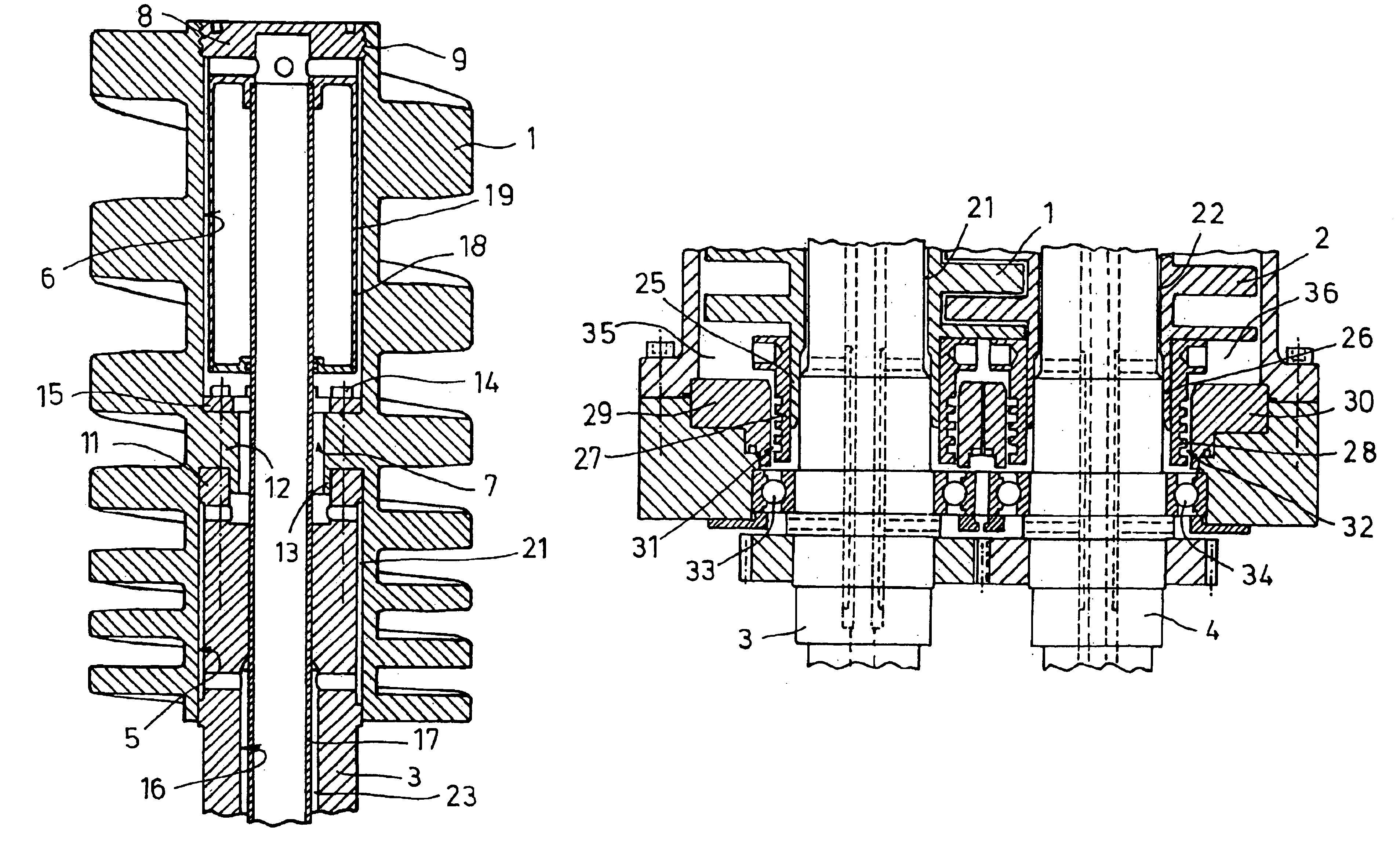
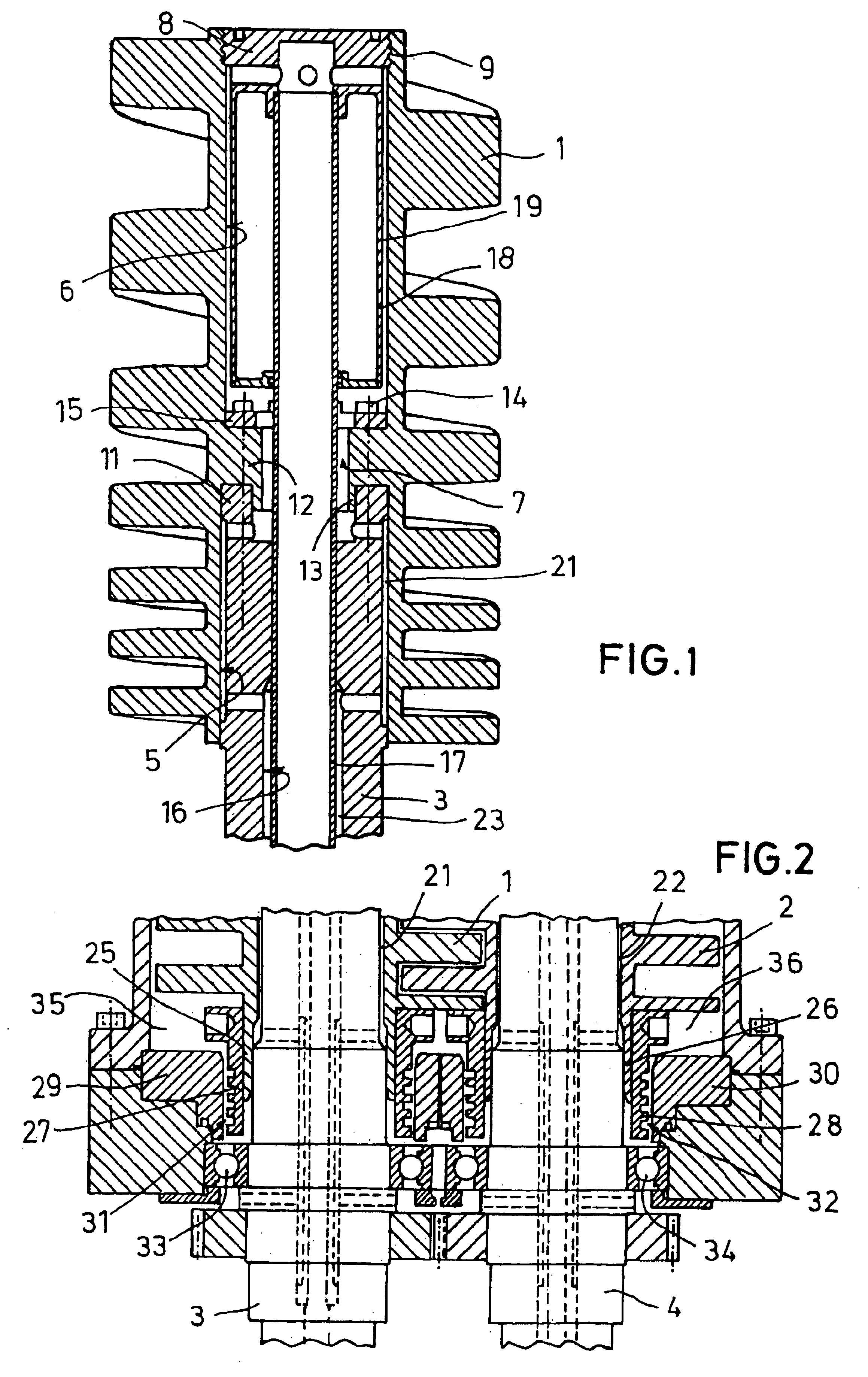
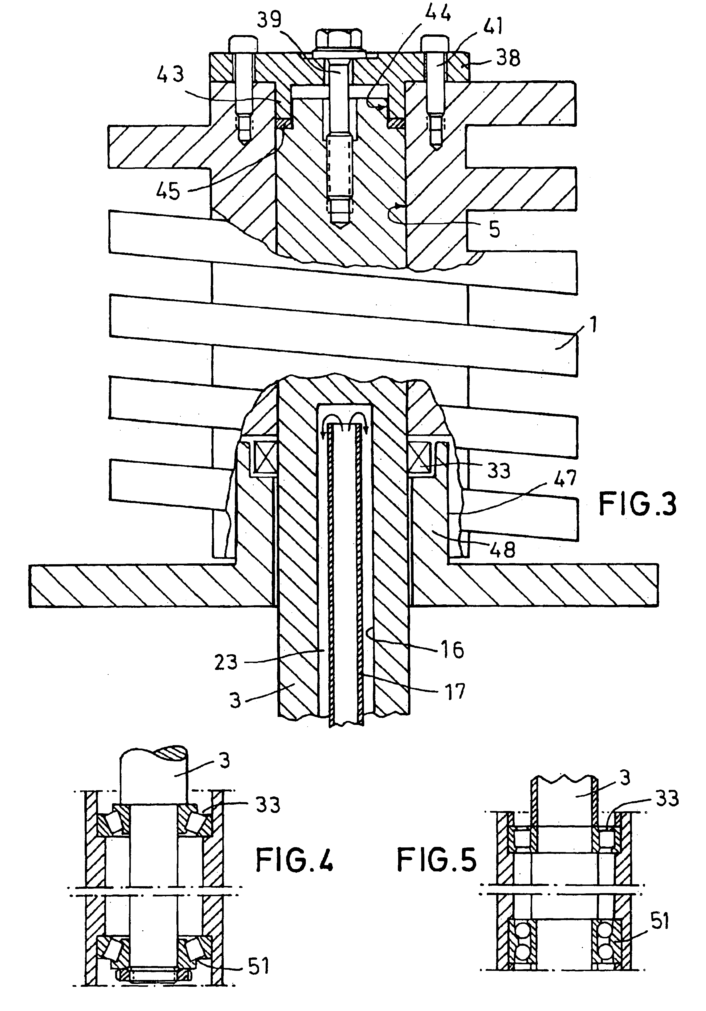
In the drawing figures the rotors are designated as 1 (resp. 1 and 2 in drawing FIG. 2) and their shafts as 3 (resp. 3, 4). The rotors are cantilevered and equipped with axial hollow bores into which the bare ends of the shafts 3, 4 extend. The rotors 1, 2 are each fixed on to the shaft ends devoid of backlash.

In the example of an embodiment in accordance with drawing FIG. 1 the rotor 1 has on its face sides two hollow bores 5 and 6 which are linked to each other approximately at the center of the rotor 1 via a more narrow bore 7. In the assembled state, the opening of the hollow bore 6 on the intake side is firmly sealed with a disk 8, which is—as depicted—screwed into the hollow bore with the aid of a thread 9, for example.

In the hollow bore 5 on the bearing side there already ends the shaft 3 which is equipped on its face side with an axially oriented collar 11. In the area of the more narrow bore 7 linking the hollow bores 5 and 6, the annular protrusion 12 extending to the insi...


PUM


Abstract

A vacuum pump has two shafts (3, 4) and two rotors (1, 2) which co-operate with each other and which are fixed to the shafts. The rotors are cantilevered on the shafts. The rotors are fixed to the shafts in a manner which is devoid of backlash, even during temperature changes. In order to achieve this, the shafts (3, 4) are made of a material having a modulus of elasticity which is as high as possible, e.g., steel. The rotors (1, 2) are made of a material having a density which is as low as possible, e.g., aluminum or a titanium alloy. Structures (8; 11, 12, 13; 14, 15; 25, 27; 38, 41; 43, 44, 45; etc.) are provided to ensure that the rotors (1, 2) are fixed to the shafts (3, 4) in a manner which is devoid of backlash at all operating temperatures.

Description

The present invention relates to a vacuum pump comprising two shafts and two rotors which co-operate with each other and which are fixed to the shafts. In this manner, the rotors are cantilevered by the shafts.The developers and manufacturers of prior pumps, screw pumps in particular, want to operate such pumps at reasonable manufacturing costs at as high as possible speeds, and with leaks through slots as small as possible, in order to attain the purpose—vacuum generation—as effectively as possible. The pre-requisites for this are precise bearings and fitting of the rotors to the shafts devoid of backlash—also in the warm state. As to the bearing, it needs to be considered that the rotors are cantilevered. This is commonly performed two bearings per shaft between which there is located a drive motor. In particular, in the instance of screw vacuum pumps such a kind of bearing has been found to be expedient, since its benefits—no seal on the intake side, more cost-effective compared ...

Claims


Application Information

Patent Timeline
IPC IPC(8): F04C18/08F04C18/16F04C29/04F04C25/02F04C29/00
CPCF04C18/084F04C29/04F04C18/16F02B39/00
Inventor KRIEHN, HARTMUTBRENNER, LOTHARBEHLING, MANFREDDREIFERT, THOMASROFALL, KLAUSENGLANDER, HEINRICHFROITZHEIM, MICHAEL
Owner LEYBOLD VAKUUM GMBH
Why Eureka
Try Eureka