Control device for multi-cylinder internal combustion engine and signaling device capable of providing same with information

a multi-cylinder internal combustion engine and control device technology, applied in the direction of electrical control, process and machine control, instruments, etc., can solve the problems of generating exhaust gas and wasting fuel, aggravating exhaust emissions, and inability to perform idle stop

Active Publication Date: 2005-06-30
MITSUBISHI HEAVY IND ENGINE & TURBOCHARGER LTD
View PDF5 Cites 33 Cited by
  • Summary
  • Abstract
  • Description
  • Claims
  • Application Information

AI Technical Summary

Problems solved by technology

Even in such a case, the internal combustion engine (hereinafter referred to simply as an engine) installed on the vehicle continues idling, posing the problems of generating an exhaust gas and wasting fuel.
Even if the vehicle is at a stop without doubt, however, it may be inappropriate to perform an idle stop from the aspects of safety and functionality.
Thus, when the engine is restarted, the activity

Method used


Image

  • Control device for multi-cylinder internal combustion engine and signaling device capable of providing same with information
  • Control device for multi-cylinder internal combustion engine and signaling device capable of providing same with information
  • Control device for multi-cylinder internal combustion engine and signaling device capable of providing same with information

Examples


embodiment 1

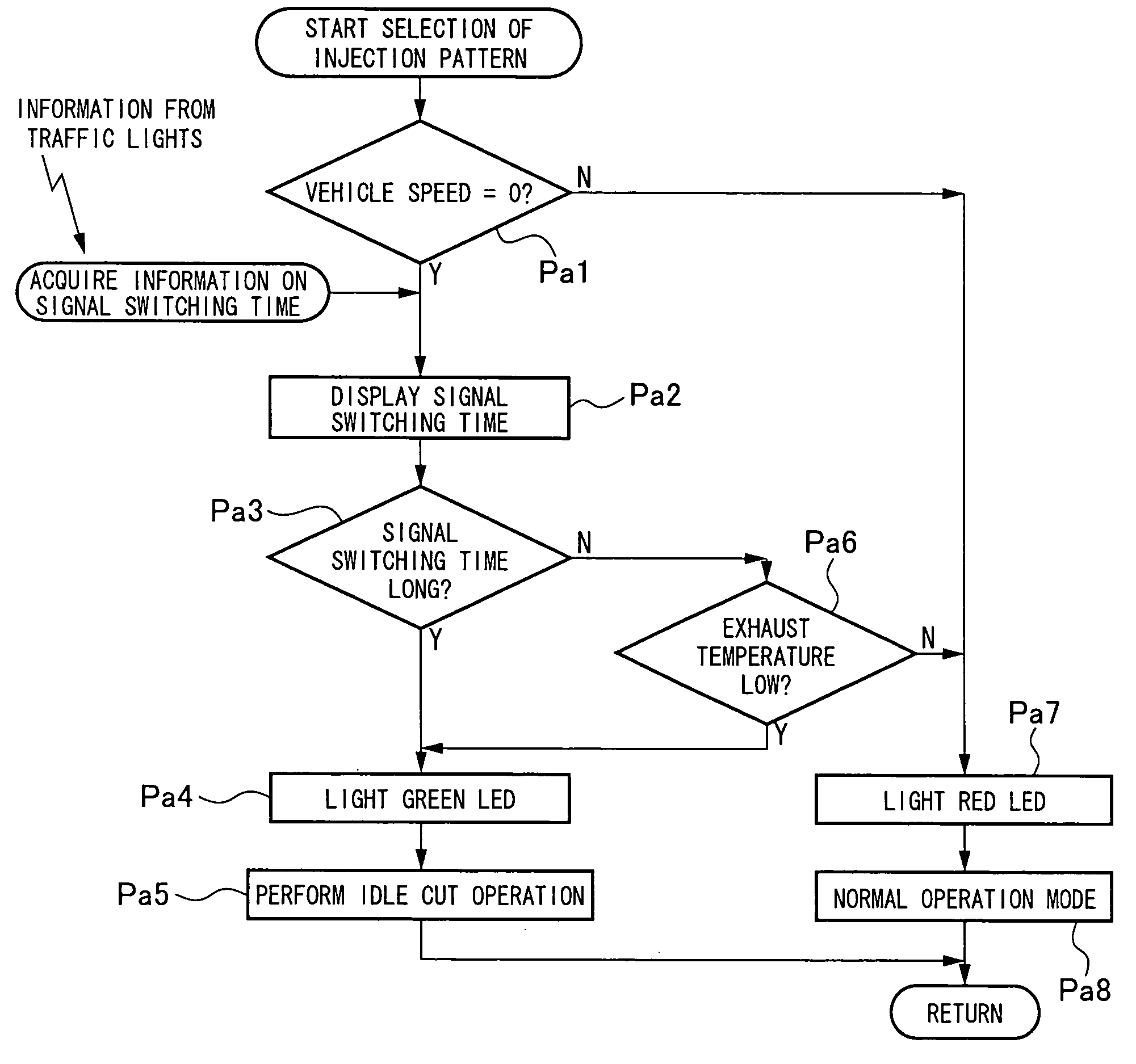
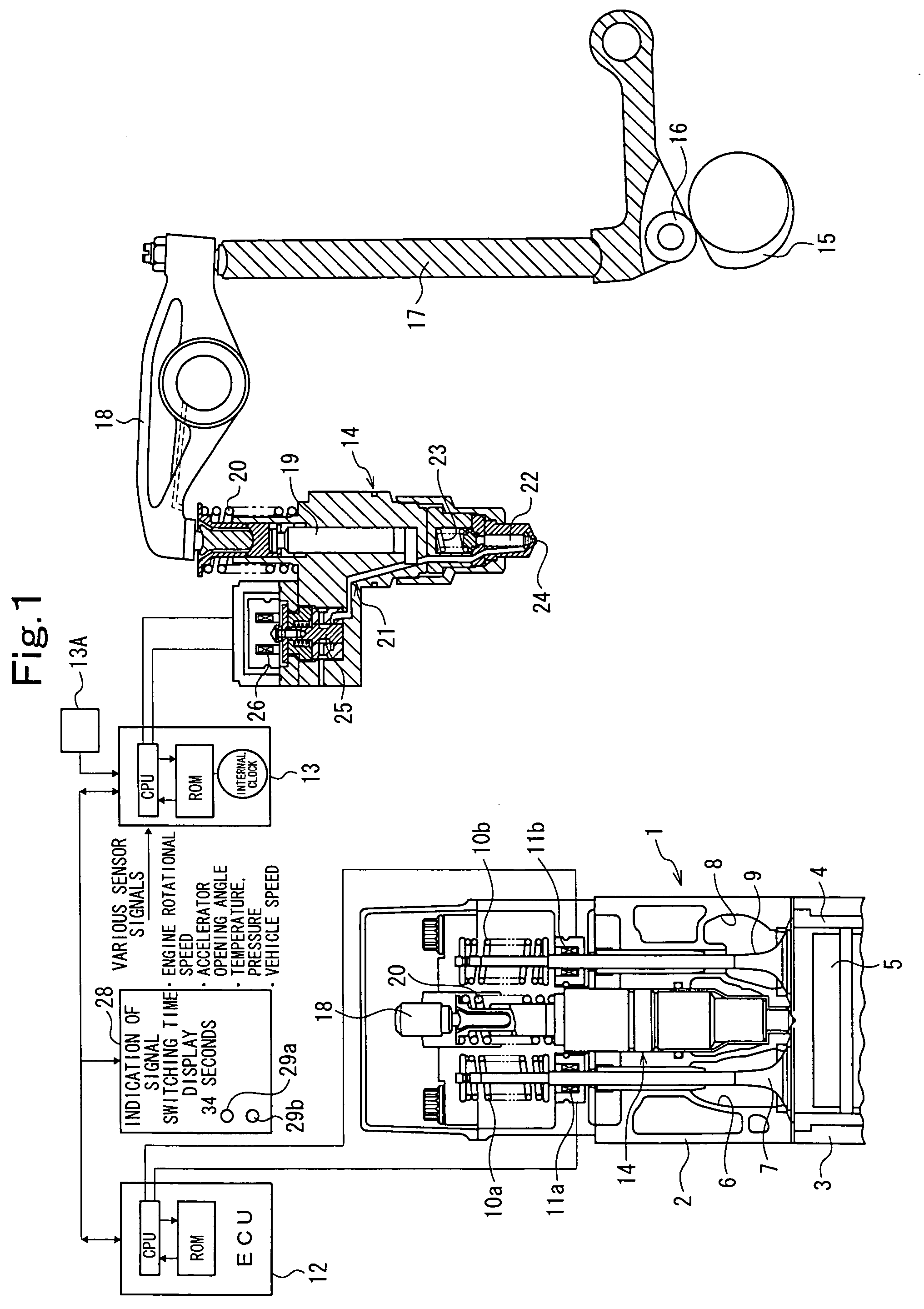
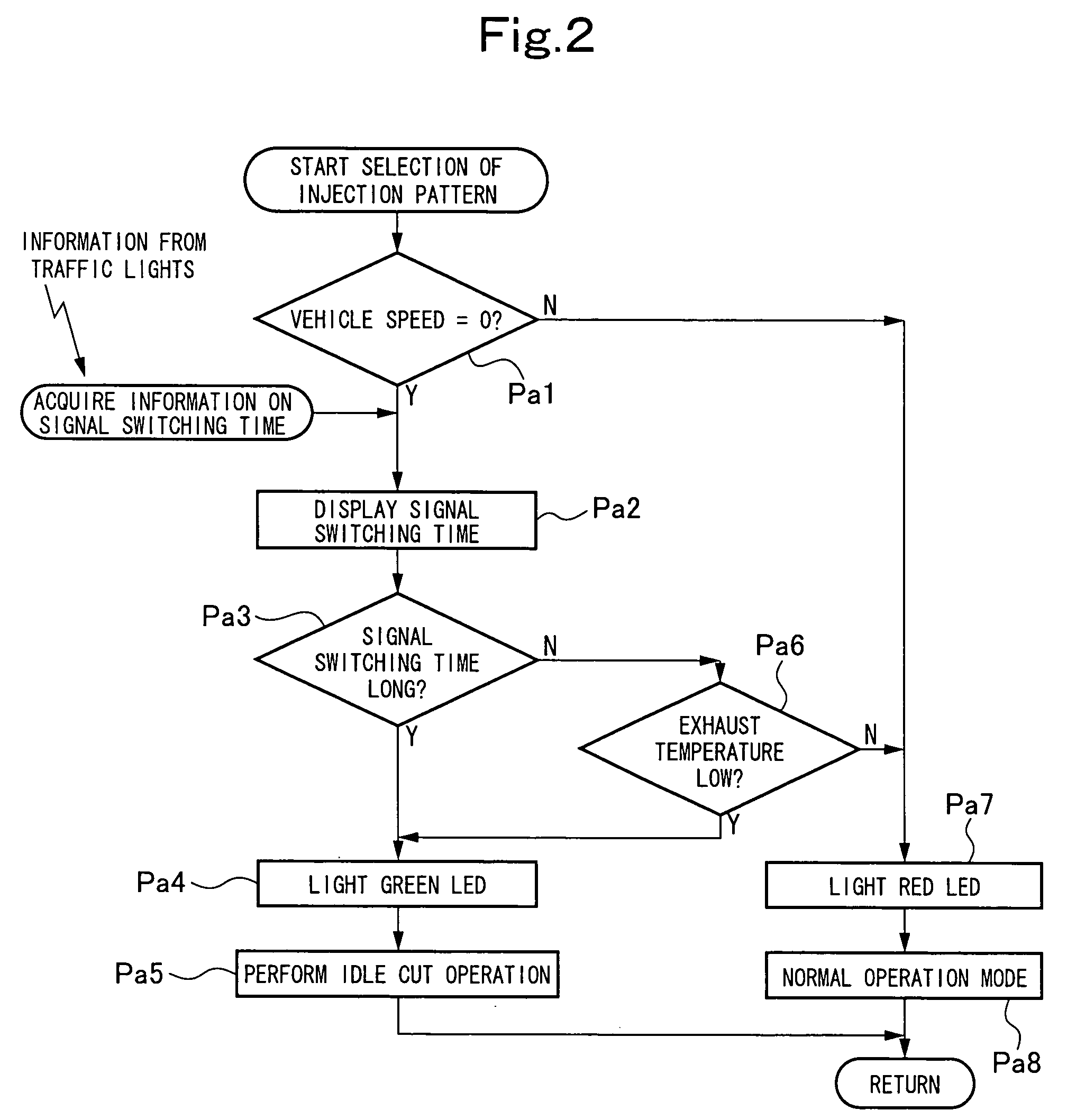
[0037]FIG. 1 is a structural explanation drawing of a multi-cylinder internal combustion engine in a vehicle, such as an automobile, showing Embodiment 1 of the present invention. FIG. 2 is a flow chart for selection of an injection pattern. FIG. 3 is a flow chart for an idle cut operation. FIG. 4 is a flow chart for determination of an idle cut cylinder. FIG. 5 is an explanation drawing of means for acquiring information on a traffic signal switching time.

[0038] As shown in FIG. 1, a multi-cylinder internal combustion engine (hereinafter referred to simply as an engine) 1 having six cylinders, for example, is composed of a cylinder head 2 and a cylinder block 3. A piston 5 is slidably housed in each cylinder of the cylinder block 3 via a cylinder liner 4.

[0039] Each cylinder of the cylinder head 2 is provided with an intake valve 7 for opening and closing an intake port 6, and an exhaust valve 9 for opening and closing an exhaust port 8. The intake valve 7 and the exhaust valve 9...

embodiment 2

[0059]FIG. 6 is a flow chart for selecting an injection pattern showing Embodiment 2 of the present invention.

[0060] In the controlling actions of the electronic control units (ECU) 12, 13 in Embodiment 1, after determination of the vehicle speed (see Step Pc1), the battery voltage is determined (see Step Pc2). If the battery voltage is high, and the signal switching time is long, the green LED is lit. If the exhaust gas temperature is low even when the signal switching time is short (see Steps Pc3 to Pc7), the green LED is lit. By lighting the green LED, recommendation for an idle cut is displayed to the driver. If the signal switching time is short, and the exhaust gas temperature is high, the red LED is lit to recommend the driver not to use an idle cut. The electronic control units, as noted above, judge only which of use and non-use of the idle cut is recommendable. Regardless of the indication by the electronic control units, the driver turns on or off a manual selector switc...

embodiment 3

[0062]FIG. 6-A is a flowchart for selecting an injection pattern showing Embodiment 3 of the present invention.

[0063] In the controlling actions of the electronic control units (ECU) 12, 13 in Embodiment 1, after determination of the vehicle speed (see Step Pca1), a manual selector switch is turned on or off at the driver's discretion (see Step Pca2). By turning on the manual selector switch, an idle cut operation is performed. By turning off the manual selector switch, a determination of whether to perform an idle cut is entrusted to the electronic control units (see Step Pca3). On this occasion, it is preferred for the driver to acquire signal switching time information visually from the signal switching time display devices 32 mounted on the traffic lights 30, as shown in FIG. 5(b). A determination of the battery voltage in Step Pca3 is not essential.

[0064] According to the present Embodiment 3, the same actions and effects as those in Embodiment 1 are obtained, except that an ...


PUM


Abstract

A control device for an engine, which includes a plurality of cylinders, an electronically controlled unit injector for injecting fuel into each cylinder, and an electronically controlled valve train for opening and closing an intake valve and an exhaust valve of each cylinder, comprises operating state detection means for detecting the operating state of the engine, and electronic control units for performing an idle cut operation, in which fuel injection into some of the cylinders is stopped, and the intake valve and the exhaust valve of the cylinder concerned are kept closed, if the signal switching time is long when the idling of the engine of a vehicle waiting at traffic lights is detected by the operating state detection means.

Description

CROSS REFERENCE TO RELATED APPLICATION [0001] The entire disclosure of Japanese Patent Application No. 2003-432215 filed on Dec. 26, 2003, including specification, claims, drawings and summary, is incorporated herein by reference in its entirety. BACKGROUND OF THE INVENTION [0002] 1. Field of the Invention [0003] This invention relates to a control device for a multi-cylinder internal combustion engine in a vehicle, such as an automobile, or a stationary multi-cylinder internal combustion engine, and a signaling device capable of providing the control device with information. More specifically, the invention relates to the control device and the signaling device preferred for a multi-cylinder internal combustion engine which can perform a cylinder number control operation permitting some of the cylinders to rest without working. [0004] 2. Description of the Related Art [0005] A vehicle, such as an automobile, is often compelled to stop transiently by traffic signals while running in...

Claims


Application Information

Patent Timeline
IPC IPC(8): F02D45/00F02D13/06F02D17/02F02D29/02F02D41/00F02D41/02F02D41/08F02D41/12F02D41/36
CPCF02B2275/14F02D13/06F02D17/02F02D41/0087F02D41/021F02D41/08Y02T10/123F02D41/1445F02D2041/001F02D2041/0012F02D2041/1412F02D2200/0804Y02T10/18F02D41/123Y02T10/12
Inventor KANEKO, TAKASHIOKAJIMA, AKIHIDE
Owner MITSUBISHI HEAVY IND ENGINE & TURBOCHARGER LTD
Why Eureka
Try Eureka