Control system for a two chamber gas discharge laser

a control system and gas discharge technology, applied in the direction of instruments, photomechanical equipment, active medium materials, etc., can solve the problems of high cost, large size, and complex construction and operation of laser systems comprised of two separate systems, and achieve the effects of increasing output power, wavelength stability and bandwidth, and pulse energy stability

Inactive Publication Date: 2006-05-02
CYMER INC
View PDF58 Cites 36 Cited by
  • Summary
  • Abstract
  • Description
  • Claims
  • Application Information

AI Technical Summary

Benefits of technology

[0005]Excimer lasers such as described in the '884 patent have during the period 1989 to 2001 become the primary light source for integrated circuit lithography. More than 1000 of these lasers are currently in use in the most modem integrated circuit fabrication plants. Almost all of these lasers have the basic design features described in the '884 patent.
[0009](4) a beam monitor for monitoring pulse energy, wavelength and bandwidth of output pulses with a feedback control system for controlling pulse energy, energy dose and wavelength on a pulse-to-pulse basis.
[0010]During the 1989-2001 period, output power of these lasers has increased gradually and beam quality specifications for pulse energy stability, wavelength stability and bandwidth have become increasingly tighter. Operating parameters for a popular lithography laser model used widely in integrated circuit fabrication include pulse energy at 8 mJ, pulse rate at 2,500 pulses per second (providing an average beam power of up to about 20 watts), bandwidth at about 0.5 pm full width half maximum (FWHM) and pulse energy stability at + / −0.35%.
[0011]When these gas discharge are used as light sources for integrated circuit fabrication they are usually operated in what is known as “burst mode” operation. For example, a laser may be operated at a repetition rate of 2,500 Hz for 0.3 seconds with pulse energies of about 8 mJ in order to scan a die spot on a silicon wafer. The laser is then “off” for a period of about 0.3 seconds while the scanner positions the wafer and the scanner optics for illumination of the next die spot. This routine continues until all of the die spots on the wafer (for example, 200 die spots) have been illuminated. Then the scanner equipment replaces the scanned wafer with another wafer. Thus, the typical laser operating cycle would be:
[0021]What is needed is a better control system for a pulse gas discharge laser for operation at repetition rates in the range of about 4,000 to 6,000 pulses per second or greater.
[0024]Feedback timing control techniques are provided for controlling the relative timing of the discharges in the two chambers with accuracy in the range of about 2 to 5 billionths of a second even in burst mode operation. This MOPA system is capable of output pulse energies approximately double the comparable single chamber laser system with greatly improved beam quality.

Problems solved by technology

These excimer lasers, when used for integrated circuit lithography, are typically operated in an integrated circuit fabrication line “around-the-clock” producing many thousands of valuable integrated circuits per hour; therefore, down-time can be very expensive.
Prior art lithography lasers typically do not provide for fast response control of bandwidth.
Laser systems comprised of two separate systems tend to be substantially more expensive, larger and more complicated to build and operate than comparable single chamber laser systems.
Therefore, commercial application of these two chamber laser systems has been limited.

Method used


Image

  • Control system for a two chamber gas discharge laser
  • Control system for a two chamber gas discharge laser
  • Control system for a two chamber gas discharge laser

Examples


Embodiment Construction

General Description

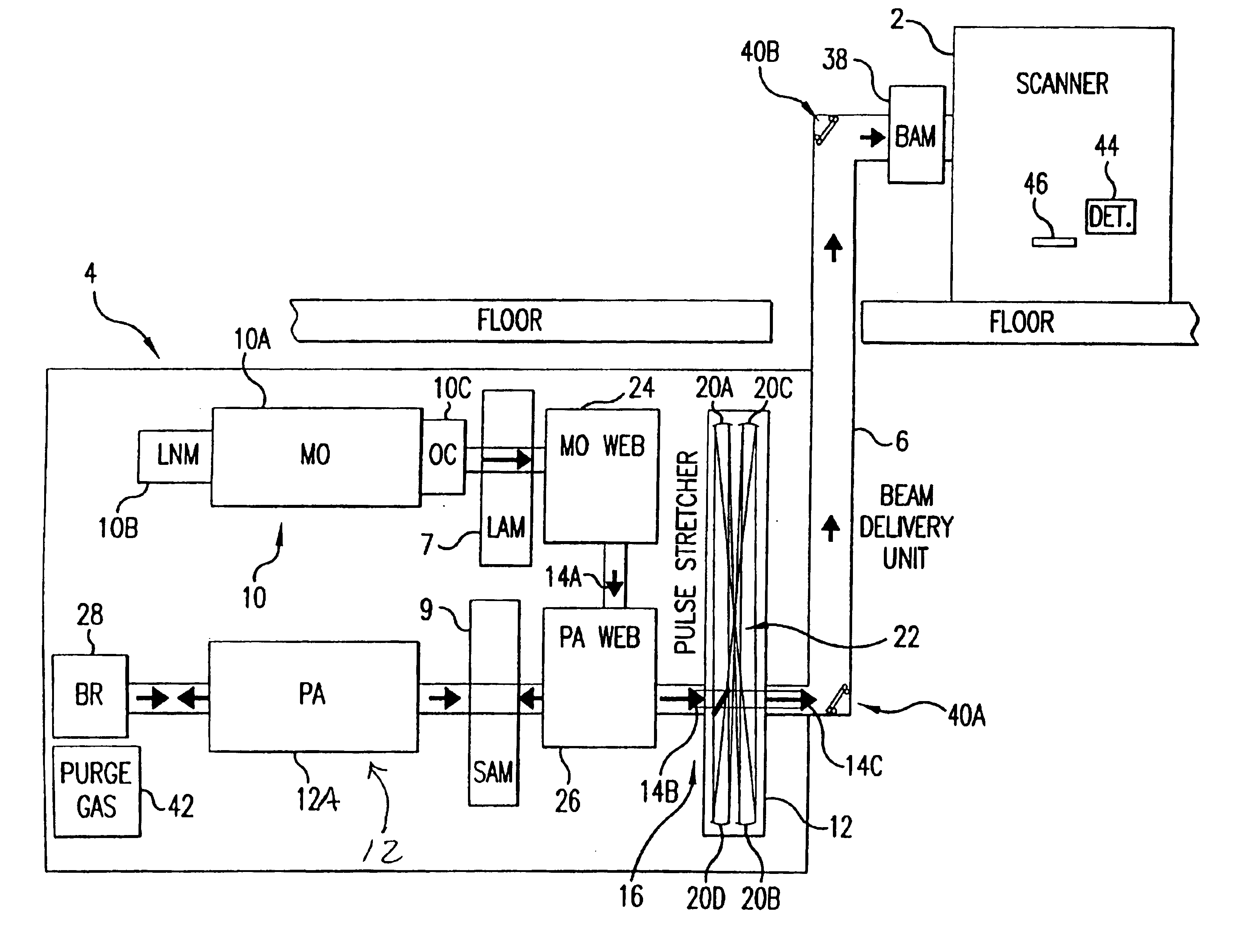
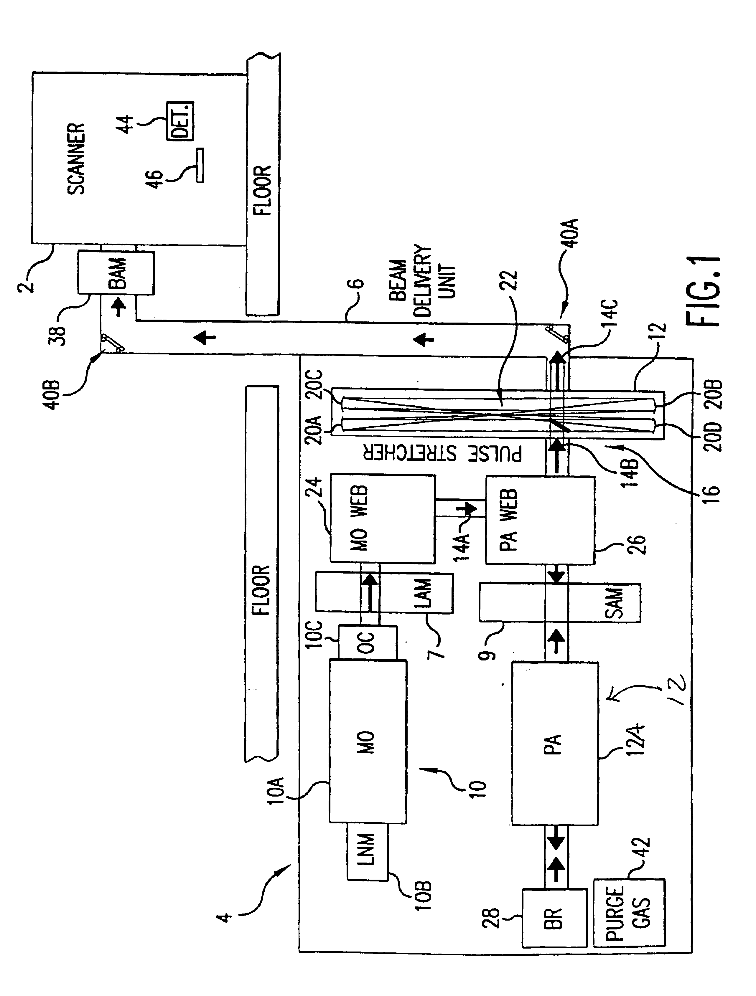
[0056]A laser system incorporating a first preferred embodiment of the present invention is shown in FIG. 1. In this embodiment a 193 nm ultraviolet laser beam is provided at the input port of a lithography machine 2 such as stepper or scanner machines supplied by Canon or Nikon with facilities in Japan or ASML with facilities in the Netherlands. This laser system includes a laser energy control system for controlling both pulse energy and accumulated dose energy output of the system at pulse repetition rates of 4,000 Hz or greater. The system provides extremely accurate triggering of the discharges in the two laser chambers relative to each other with both feedback and feed-forward control of the pulse and dose energy.

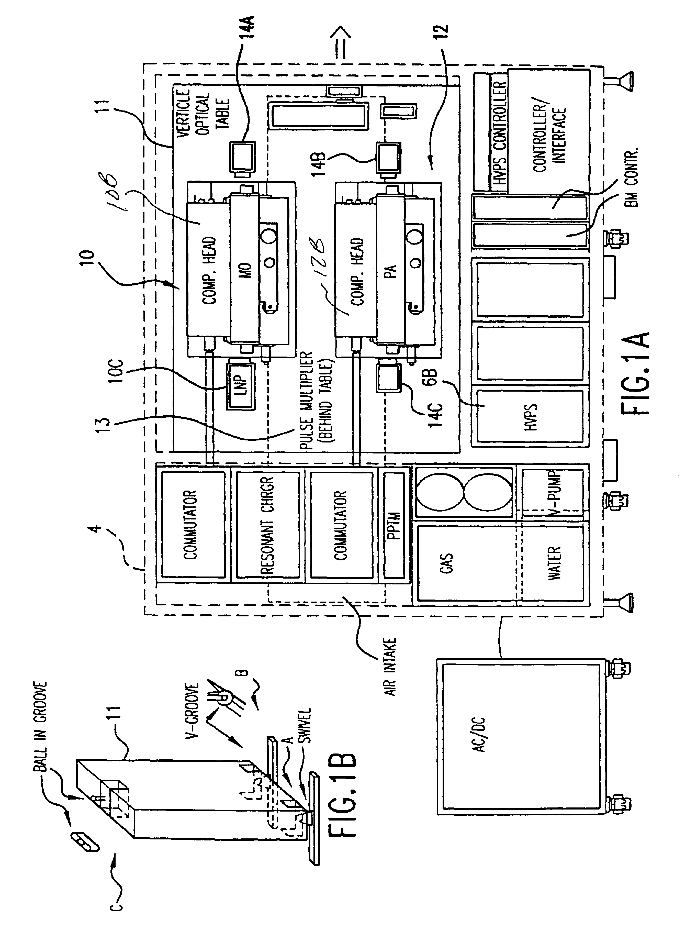
[0057]In this case the main components of the laser system 4 are installed below the deck on which the scanner is installed. However, this laser system includes a beam delivery unit 6, which provides an enclosed beam path for delivering the laser be...


PUM


Abstract

The present invention provides a control system for a modular high repetition rate two discharge chamber ultraviolet gas discharge laser. In preferred embodiments, the laser is a production line machine with a master oscillator producing a very narrow band seed beam which is amplified in the second discharge chamber.
Novel control features specially adapted for a two-chamber gas discharge laser system include: (1) pulse energy controls, with nanosecond timing precision (2) precision pulse to pulse wavelength controls with high speed and extreme speed wavelength tuning (3) fast response gas temperature control and (4) F2 injection controls with novel learning algorithm.

Description

[0001]The present invention claims priority to U.S. application Ser. No. 60 / 454,029 filed Mar. 11, 2003 and is a continuation-in-part of U.S. application Ser. No. 10 / 384,967 filed Mar. 8, 2003 now U.S. Pat. No. 6,904,073, which is a continuation-in-part of Ser. No. 10 / 210,761 U.S. Pat. No. 6,690,704 filed Jul. 31, 2002, Ser. No. 10 / 187,336 filed Jun. 28, 2002, of Ser. No. 10 / 141,216 U.S. Pat. No. 6,693,939 filed May 7, 2002, of Ser. No. 10 / 036,676, U.S. Pat. No. 6,882,674 filed Dec. 21, 2001, Ser. No. 10 / 036,727 filed Dec. 21, 2001 U.S. Pat. No. 6,865,210, Ser. No. 10 / 006,913 filed Nov. 29, 2001 U.S. Pat. No. 6,535,531, Ser. No. 10 / 000,991 U.S. Pat. No. 6,795,474 filed Nov. 14, 2001, Ser. No. 09 / 943,343 U.S. Pat. No. 6,567,450, filed Aug. 29, 2001, Ser. No. 09 / 854,097 U.S. Pat. No. 6,757,316, filed May 11, 2001, Ser. No. 09 / 848,043 U.S. Pat. No. 6,549,551, filed May 3, 2001, and Ser. No. 09 / 829,475 U.S. Pat. No. 6,765,945 filed Apr. 9 2001, all of which are incorporated herein by re...

Claims


Application Information

Patent Timeline
Patent Type & Authority Patents(United States)
IPC IPC(8): H01S3/22H01S3/03H01S3/036H01S3/1055H01S3/223H01S3/225H01S3/23
CPCG03F7/70025G03F7/70041H01S3/036H01S3/1055H01S3/0057H01S3/2333H01S3/09702H01S3/2258H01S3/0381H01S3/03H01S3/225
Inventor FALLON, JOHN P.RULE, JOHN A.JACQUES, ROBERT N.LIPCON, JACOBSANDSTROM, RICHARD L.PARTLO, WILLIAM N.ERSHOV, ALEXANDER I.ISHIHARA, TOSHIHIKOMEISNER, JOHNNESS, RICHARD M.MELCHER, PAUL C.
Owner CYMER INC
Why Eureka
Try Eureka