Constant current dimming apparatus for LED lamp

a technology of led lamps and dimming devices, which is applied in the direction of lighting apparatus, electrical equipment, light sources, etc., can solve the problems of excessive device loss, flickering in the dimming process, and the inability to achieve a very low dimming depth in the above-dimming solution, etc., to achieve a wide range of dimming, high conversion efficiency, and output power.

Inactive Publication Date: 2020-08-27
ADPOWER TECH WUXI
View PDF0 Cites 0 Cited by
  • Summary
  • Abstract
  • Description
  • Claims
  • Application Information

AI Technical Summary

Benefits of technology

[0017]A signal generated by the present invention is formed by combining a variable frequency signal with a power conversion line. A wide dimming range is achieved, and a dimming depth can reach 1‰ of a rated current. An output ripple of the power converter is small, and the LED lamp is free of flicker during the dimming process and after the dimming is stable. An output ripple is small during the dimming, and the power converter can achieve higher conversion efficiency and output power using a lower switching frequency.

Problems solved by technology

Although the anti-interference capability is strong and the dimming range is wide, the dimming method has a small number of pulses output by a DC / DC controller during enabling time of the dimming signal in the case of a small duty ratio; in the dimming process, the output current exhibits a stepped change with the change of the number of the pulses, which leads to the flicker in the dimming process, and if the operating frequency of the power conversion module is increased, the device loss will be excessive.
Therefore, the above dimming solutions cannot achieve a very low dimming depth, and the disadvantages are more obvious especially when a lower operating frequency is applied under some large power requirements.

Method used


Image

  • Constant current dimming apparatus for LED lamp
  • Constant current dimming apparatus for LED lamp
  • Constant current dimming apparatus for LED lamp

Examples


embodiment 1

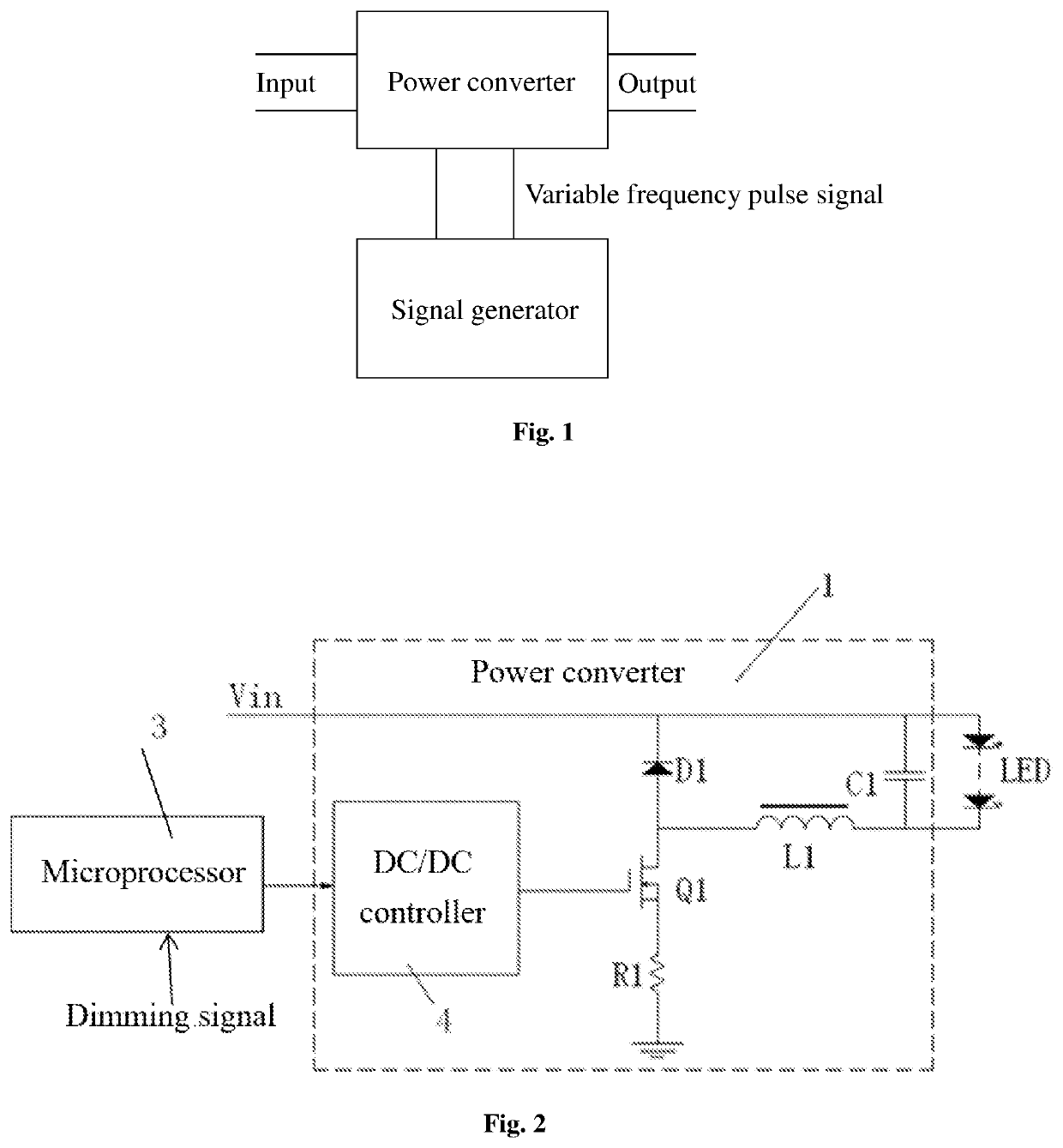
[0033]Based on the above technology, as shown in FIG. 2, the voltage stabilizing filter element may further include an inductor L1. The drain of the MOS transistor Q1 is connected in parallel to an anode of the first diode D1 and one end of the inductor L1, the input voltage is connected in parallel to a cathode of the first diode D1 and the end of the first capacitor C1, and the other end of the inductor L1 is connected to the other end of the first capacitor C1.

embodiment 2

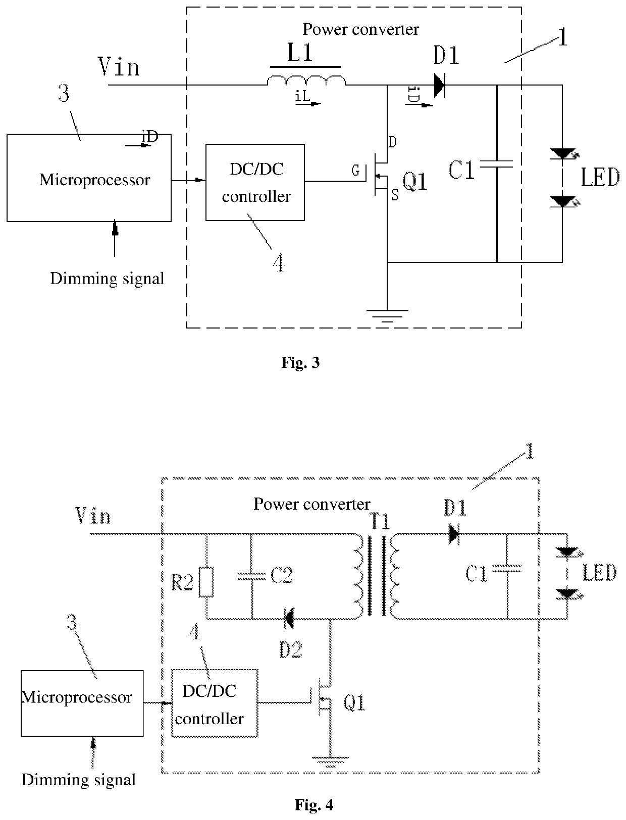
[0034]Based on the above technology, as shown in FIG. 3, the drain of the MOS transistor Q1 is connected in parallel to one end of the inductor L1 and the anode of the first diode D1, and the other end of the inductor L1 is connected to the input voltage; the cathode of the first diode D1 is connected to the end of the first capacitor C1, and the other end of the first capacitor C1 is further connected to the source of the MOS transistor Q1.

embodiment 3

[0035]Based on the above technology, as shown in FIG. 4, the voltage stabilizing filter element further includes a transformer T1, a second diode D2, a second capacitor C2, and a second resistor R2, where the input voltage is connected in parallel to one end of the second capacitor C2, one end of the second resistor R2, and one end of a primary coil of the transformer T1; the other end of the second capacitor C2 and the other end of the second resistor R2 are connected in parallel to a cathode of the second diode D2; the drain of the MOS transistor Q1 is connected in parallel to the anode of the first diode D1 and the other end of the primary coil of the transformer T1; one end of a secondary coil of the transformer T1 is connected to the anode of the first diode D1, the cathode of the first diode D1 is connected to the end of the first capacitor C1, and the other end of the secondary coil of the transformer T1 is connected to the other end of the first capacitor C1.

[0036]Referring ...


PUM


Abstract

A constant current dimming apparatus for an LED lamp includes a signal generator and a power converter, where an input end of the signal generator is externally connected to a dimming device; an output end of the signal generator is connected to the power converter; an input end of the power converter is connected to an input voltage; and an output end of the power converter is connected to a positive electrode end and a negative electrode end of the LED lamp. The signal generator is used for transmitting a variable frequency pulse signal to the power converter upon receipt of a dimming signal of the dimming device. According to the present invention, a wide dimming range is achieved, and a dimming depth can reach 1‰ of a rated voltage or rated current.

Description

CROSS-REFERENCE TO PRIOR APPLICATION[0001]This application claims the benefit of Chinese Patent Application No. 201910133012.4 filed on Feb. 22, 2019, the contents of which are incorporated herein by reference.TECHNICAL FIELD[0002]The present invention relates to the field of LED illumination, and in particular, to a constant current dimming apparatus for an LED lamp, for achieving deep dimming.BACKGROUND ART[0003]At present, dimming solutions applied to a LED driving power source are implemented mainly in the following methods: The first method is analog dimming, that is, an output current or voltage continuously changes with an analog dimming signal. This method has the advantages that there is no flicker in the dimming process and after the dimming is stable, but the dimming method is easily disturbed during the dimming and a dimming range is narrow and is generally 5%-100%, and flicker occurs easily when the dimming range is less than 5%. The second method is pulse width modulat...

Claims


Application Information

Patent Timeline
Patent Type & Authority Applications(United States)
IPC IPC(8): H05B45/335H05B45/345H05B45/10H05B45/325H05B44/00
CPCH05B45/10H05B45/335H05B45/325H05B45/345H05B45/3725
Inventor WANG, SHIJIEHU, SENXU, RUOPENG
Owner ADPOWER TECH WUXI
Why Eureka
Try Eureka