
Backlight module and light modulation method thereof

A backlight module and light-emitting unit technology, applied in the direction of optics, light source, electric light source, etc., can solve the problems of small dimming range, reduced circuit efficiency, and limited dimming range, and achieve the effect of increasing the dimming range

Inactive Publication Date: 2009-02-11
INNOLUX CORP
View PDF0 Cites 4 Cited by
  • Summary
  • Abstract
  • Description
  • Claims
  • Application Information

AI Technical Summary

Problems solved by technology

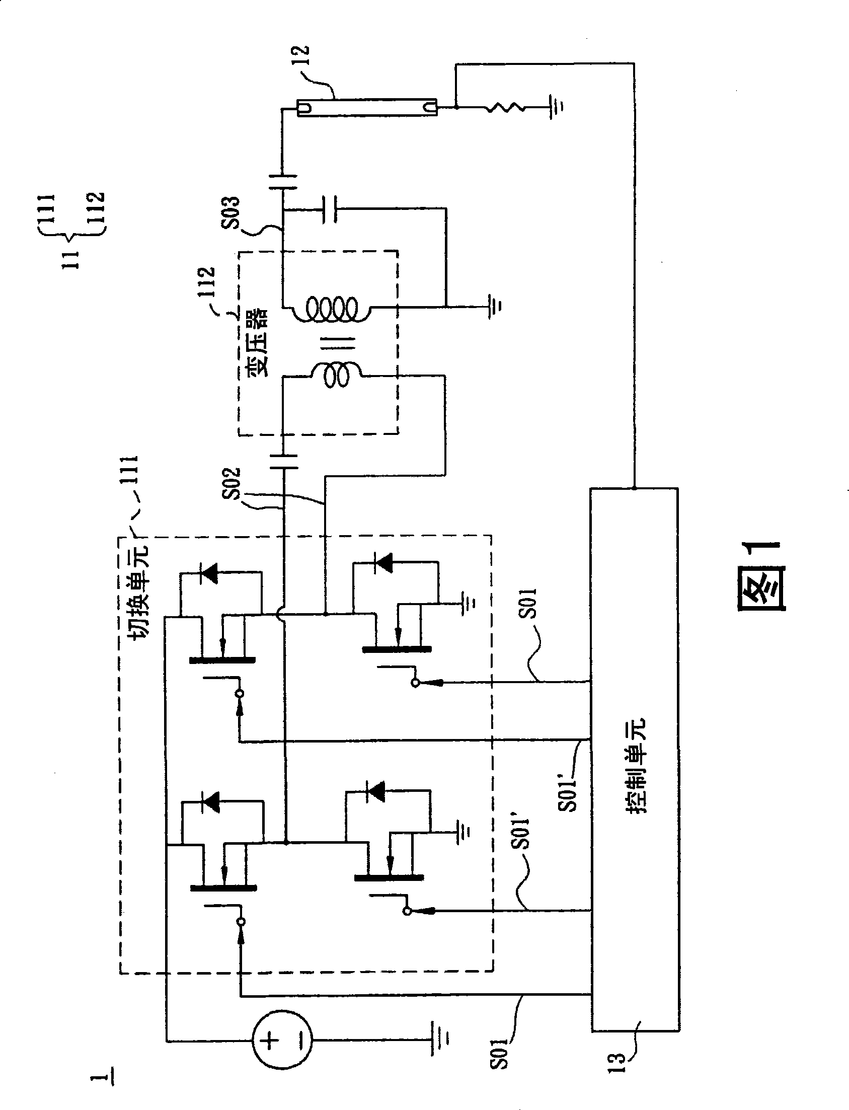
[0005] However, the amplitude dimming method is accompanied by limitations such as the difficulty in designing the electromagnetic interference filter at the power supply end of the backlight module 1, the reduction of circuit efficiency due to the lack of zero-voltage switching of the switching unit, and the limitation of the dimming range due to the input voltage of 24 volts. , it can be seen that the biggest influence is that the dimming range is not large

Method used


Image

  • Backlight module and light modulation method thereof
  • Backlight module and light modulation method thereof
  • Backlight module and light modulation method thereof

Examples


Embodiment Construction

[0019] A backlight module and a dimming method thereof according to preferred embodiments of the present invention will be described below with reference to related drawings.

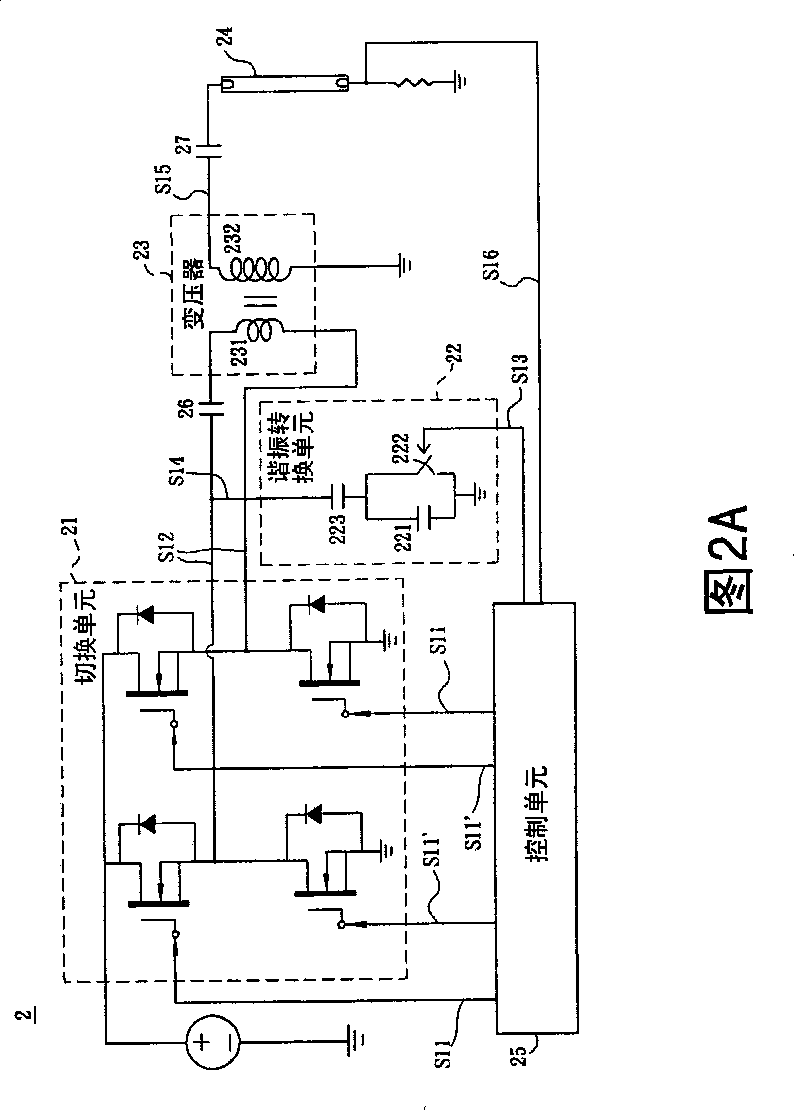
[0020] As shown in FIG. 2A , a backlight module 2 according to the first preferred embodiment of the present invention includes a switching unit 21 , a resonant converting unit 22 , a transformer 23 and a light emitting unit 24 . In addition, the backlight module 2 of this embodiment further includes a control unit 25 .

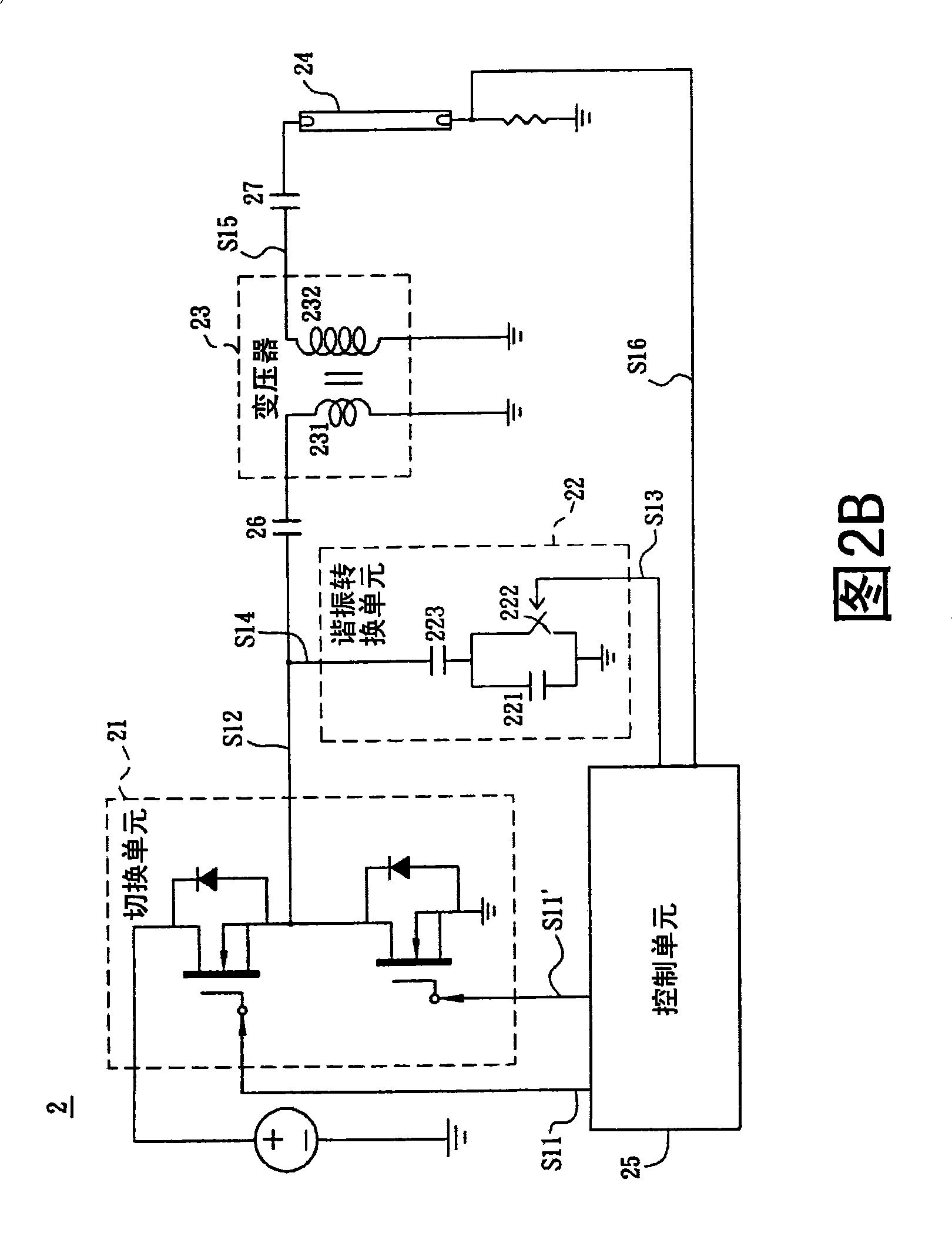
[0021] In this embodiment, the switching unit 21 includes a bridge switching circuit, which generates a switching signal S12 according to the first control signals S11, S11'. The bridge switching circuit of this embodiment can be implemented as a full bridge switching circuit (as shown in FIG. 2A) or a half bridge switching circuit (as shown in FIG. 2B). Here, the full bridge switching circuit is taken as an example, and As a result, the first control signals S11 and S11' are converte...


PUM


Abstract

A backlight module includes a switching unit, a resonance converting unit, a transformer and a lightening unit. The switching unit generates a switching signal according to a first control signal; the resonance converting unit is electrically connected with the switching unit for receiving the switching signal, and is provided with a first energy storing component and a switch component for controlling the switch component according to a second control signal and enabling the resonance converting unit to generate a resonance converting signal; the transformer is provided with a primary side winding and a secondary side winding, wherein the primary side winding is electrically connected with the resonance converting unit and the switching unit, and the transformer generates a driving signal according to the resonance converting signal and the switching signal; and the lightening unit is electrically connected with the secondary side winding and driven according to the driving signal.

Description

technical field [0001] The invention relates to a backlight module and a dimming method thereof, in particular to a backlight module and a dimming method thereof combining amplitude and burst mode dimming functions. Background technique [0002] With the advent of the digital age, the technology of liquid crystal display devices has grown rapidly and has become an indispensable electronic product. Therefore, the requirements for the technology and functions of liquid crystal display devices are also getting higher and higher. [0003] Generally speaking, a liquid crystal display device mainly includes a liquid crystal display panel and a backlight module. Among them, the liquid crystal display panel mainly has two substrates and a liquid crystal layer sandwiched between the two substrates; and the backlight module emits uniform light to distribute on the surface of the liquid crystal display panel. Traditionally, a cold cathode fluorescent lamp (CCFL) is used as the backligh...

Claims


Application Information

Patent Timeline
Patent Type & Authority Applications(China)
IPC IPC(8): G02F1/13357G09G3/34G09G3/36H05B41/36H05B41/38G02F1/1335
Inventor 赖建丞王文哲陈世明
Owner INNOLUX CORP
Learn More