Dimming method, adjuster and dimming system

A regulator and dimming switch technology, applied in the field of regulators, dimming systems, and dimming methods, can solve the problems of rapid discharge, insignificant changes in brightness, and insignificant changes in voltage across load lamps, and reduce power consumption. , The driving cycle is stable, and the effect of increasing the dimming range

Active Publication Date: 2015-04-29
SCHNEIDER ELECTRIC (AUSTRALIA) PTY LTD
View PDF4 Cites 5 Cited by
  • Summary
  • Abstract
  • Description
  • Claims
  • Application Information

AI Technical Summary

Problems solved by technology

However, for CFL and LED type loads, due to the low power of the load lamp and the internal rectifier bridge circuit, this type of load will appear in a high impedance state, and the charge stored in the safety capacitor cannot be in each sine wave. Rapid discharge in half a cycle leads to insignificant changes in the voltage across the load lamp, so the brightness change in the dimming process is also insignificant

Method used


Image

  • Dimming method, adjuster and dimming system
  • Dimming method, adjuster and dimming system
  • Dimming method, adjuster and dimming system

Examples


Embodiment 1

[0037] An embodiment of the present invention provides a dimming method, which may specifically be a dimming method for a load characteristic adjuster.

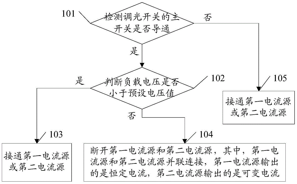
[0038] A dimming method, comprising: detecting the conduction of the main switch of the dimming switch; when the main switch is conducting, judging whether the load voltage is less than a preset voltage value, if less than, turning on the first current source, if not less than , then disconnect the first current source and the second current source; when the main switch is disconnected, connect the first current source or the second current source, the first current source and the second current source are connected in parallel, the output of the first current source is a constant current, and the output of the second current source is a variable current.

[0039] see figure 1 , the specific process can be as follows:

[0040] 101. Determine whether the main switch of the dimmer switch is turned on;

[0041] If the main sw...

Embodiment 2

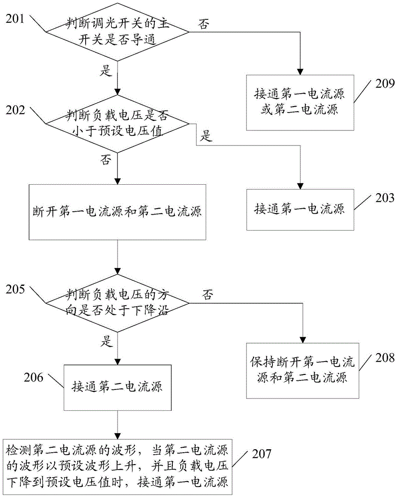
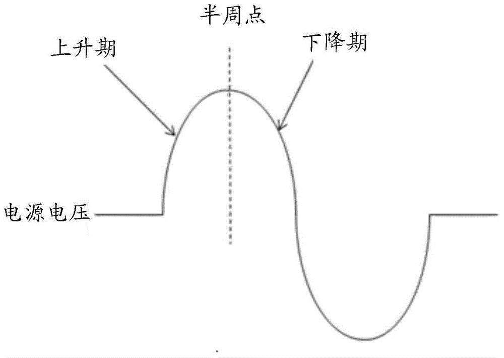
[0056] For ease of understanding, another embodiment of the dimming method provided by the embodiment of the present invention is introduced below. It can be understood that when the load voltage is not less than the preset voltage value, after the first current source and the second current source are disconnected, the first current source and the second current source can also be controlled by detecting the direction of the load voltage. Under different load voltage directions, the dimmer switch is in different working modes, and the first current source and the second current source can be controlled in different ways. see figure 2 , the specific process can be as follows:

[0057] 201. Determine whether the main switch of the dimmer switch is turned on;

[0058] If the main switch of the dimmer switch is turned on, then execute step 202 to determine whether the load voltage is less than the preset voltage value; if the main switch of the dimmer switch is not turned on, ...

Embodiment 3

[0077] In order to better understand the above method, this embodiment also provides an adjuster, which may be specifically a load characteristic adjuster, for details, please refer to Figure 4 .

[0078] A regulator, including: a first current source 401, a second current source 402, and a detection controller 403; wherein, the first current source 401 and the second current source 402 are connected in parallel, and the output of the first current source 401 is a constant current , the output of the second current source 402 is a variable current, the first current source 401 and the second current source 402 are respectively used to discharge the input capacitance of the load; the detection controller 403 is used to detect the conduction of the main switch of the dimmer switch state, when the main switch is turned on, it is judged whether the load voltage is less than the preset voltage value, if it is less than, the first current source 401 is connected, if not, the first ...


PUM


Abstract

The embodiment of the invention discloses a dimming method, an adjuster and a dimming system. The dimming method comprises the following steps: detecting the conducting situation of a main switch of a dimming switch; controlling a first current source and a second current source according to the conducting situation of the main switch, wherein when the main switch is conducted, judging whether the load voltage is less than a preset voltage value or not; if the load voltage is less than the preset voltage value, switching on the first current source; if the load voltage is not less than the preset voltage value, switching off the first current source and the second current source; when the main switch is switched off, switching on the first current source or the second current source, wherein the first current source and the second current source are in parallel connection, the first current source outputs a constant current, and the second current source outputs a variable current. The dimming method, the adjuster and the dimming system can increase the dimming range, reduce power consumption, and can guarantee flicker-free or shimmering loading under the circumstance of switching off the dimming switch.

Description

technical field [0001] The invention relates to the field of dimming switches, in particular to a dimming method, an adjuster and a dimming system. Background technique [0002] At present, most of the dimmer switches on the market are designed for the two-wire system, that is, there are only live wires and load wires in the cavity of the dimmer switch, and there is no neutral wire. In order to reduce the loss of the dimming switch, the chopping type dimming switch is designed as a zero-crossing switch. For example, in the leading-edge phase-cutting mode, the dimming switch will be disconnected at the current zero-crossing point; in the trailing-edge phase-cutting mode Down, the dimmer switch will be closed at the voltage zero crossing. In order to ensure that the dimmer switch can work normally, it is necessary to ensure a stable zero-crossing point in each dimming half cycle. Since the control circuit of the dimmer switch requires a certain amount of power consumption, w...

Claims


Application Information

Patent Timeline
Patent Type & Authority Applications(China)
IPC IPC(8): H05B37/02
CPCY02B20/40
Inventor 冯伟刘国雄
Owner SCHNEIDER ELECTRIC (AUSTRALIA) PTY LTD
Why Eureka
Try Eureka