
LED controller, LED control device and LED control method

A technology of light-emitting diodes and control devices, which can be applied to electrical components and other directions, and can solve problems such as flickering of light-emitting diode units and increasing duty cycle.

Active Publication Date: 2021-03-19
NOVATEK MICROELECTRONICS CORP
View PDF5 Cites 0 Cited by
  • Summary
  • Abstract
  • Description
  • Claims
  • Application Information

AI Technical Summary

Problems solved by technology

Therefore, if figure 2 As shown, when the period of the vertical synchronous signal VSYNC decreases while the luminance information of the data signal DATA remains unchanged, the duty cycle of the control signal CS first increases from the target value and then decreases to the target value, causing the LED unit 14 to flicker
similarly, as in image 3 As shown, when the period of the vertical synchronous signal VSYNC increases while the brightness information of the data signal DATA remains unchanged, the duty cycle of the control signal CS first decreases from the target value and then increases to the target value, causing the LED unit 14 to flicker

Method used


Image

  • LED controller, LED control device and LED control method
  • LED controller, LED control device and LED control method
  • LED controller, LED control device and LED control method

Examples


Embodiment Construction

[0037] The present invention will be described in detail below in conjunction with the accompanying drawings and embodiments.

[0038] Before the present invention is described in detail, it should be noted that in the following description, similar elements are denoted by the same numerals.

[0039] refer to Figure 4 , the first embodiment of the LED controller 2 of the present invention is used with a video source 7 , a current source 8 and a LED group 9 . The video source 7 generates a vertical synchronization signal VSYNC, a data signal DATA, a first clock signal FCLK1 and a second clock signal FCLK2. The vertical synchronization signal VSYNC carries image frequency information, and its frequency is variable (for example, within the range of 70 Hz to 144 Hz). The data signal DATA carries brightness information and delay information. The frequency of the first clock signal FCLK1 is fixed (for example, 12 MHz). The frequency of the second clock signal FCLK2 is variable ...


PUM


Abstract

The invention provides a light emitting diode controller, a control device and a control method. The light emitting diode controller is used with a video source and at least one light emitting diode unit. The video source generates a data signal and a vertical synchronization signal. The light emitting diode controller comprises a control signal generator and a driver. The control signal generatorperforms pulse width modulation according to a first clock signal, a second clock signal and the data signal to generate at least one control signal. The first clock signal and the second clock signal are independent of the vertical synchronization signal. The driver generates at least one driving signal according to the control signal. The drive signal is related to the light emission of the light emitting diode unit, whereby the light emitting diode unit does not flicker when the period of the vertical synchronization signal changes.

Description

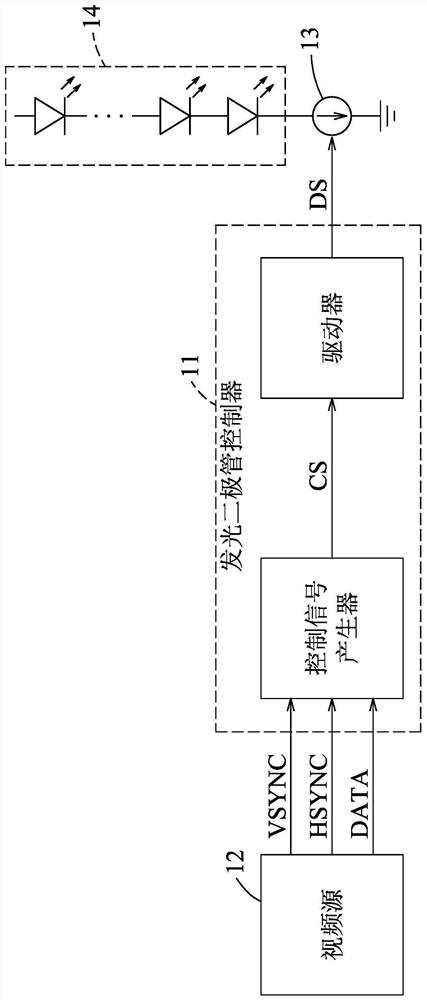
technical field [0001] The invention relates to the control of light emitting diodes, in particular to a light emitting diode controller, a light emitting diode control device and a light emitting diode control method. Background technique [0002] refer to figure 1 , the existing LED controller 11 receives a vertical synchronization signal VSYNC, a horizontal synchronization signal HSYNC and a data signal DATA from a video source 12 . The vertical synchronization signal VSYNC carries image frequency information. The horizontal synchronization signal HSYNC carries line frequency information. The data signal DATA carries brightness information and delay information. The existing light emitting diode controller 11 performs pulse width modulation according to the vertical synchronization signal VSYNC and the data signal DATA to generate a control signal CS, and generates a driving signal DS according to the control signal CS to drive a current source 13 to provide a current ...

Claims


Application Information

Patent Timeline
Patent Type & Authority Applications(China)
IPC IPC(8): H05B47/165
CPCH05B47/165H05B45/325Y02B20/40
Inventor 赖韦任许能傑丁振国叶刚帆
Owner NOVATEK MICROELECTRONICS CORP
Learn More