A separate power-taking mechanism of an intelligent switch, its connecting device, adapter part and lamp

A technology of intelligent switch and switch part, which is applied in the parts, lighting devices, circuit layout and other directions of lighting devices, can solve the problems of electricity consumption, emerging LED lamps are not easy to form loops, and the lights are turned off during the day and flicker.

Active Publication Date: 2020-10-27
速诺光电科技(常州)有限公司
View PDF4 Cites 0 Cited by
  • Summary
  • Abstract
  • Description
  • Claims
  • Application Information

AI Technical Summary

Problems solved by technology

[0002] With the advancement of science and technology, intelligent control is getting closer and closer to our production and life. Among them, switches in production sites and home lighting systems have also become intelligent, changing from mechanical switches to touch-type intelligent control switches, which can achieve more Multifunctional, but at the same time, the smart switch also needs a power supply to support its work. Since the backlight and indicator functions are generally required after the light is turned off, it consumes more electricity than when the light is turned on. In order to achieve continuous and stable power supply for the switch, the existing wiring is generally In the two-wire system, when the lights are turned off, the switching power supply is generally obtained by forming a circuit through the lamps. The lamps have currents passing through them, which causes the lights to flicker when they are turned off. Also, it is not easy to form a circuit with the emerging LED lamps, which still needs to be developed. solve

Method used


Image

  • A separate power-taking mechanism of an intelligent switch, its connecting device, adapter part and lamp
  • A separate power-taking mechanism of an intelligent switch, its connecting device, adapter part and lamp
  • A separate power-taking mechanism of an intelligent switch, its connecting device, adapter part and lamp

Examples


Embodiment Construction

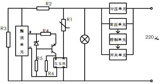
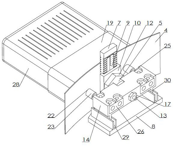
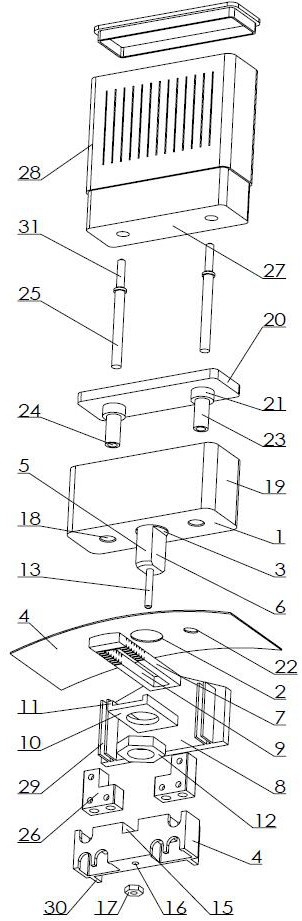
[0021] Examples of the present invention figure 1 , 2 , 3, the smart switch split power-taking mechanism includes a switch part and a lamp part, the switch part is a device located at the switch position, the lamp part is a device located at the lamp position, the switch part is provided with a switch unit, a control unit, Unit, voltage division unit, the input end of the voltage division unit is connected to the live wire of the mains input, the output end of the voltage division unit is connected to the wire from the switch to the lamp, and the voltage division unit must obtain voltage division at both ends to provide voltage for the voltage transformation unit. The voltage unit can be a resistor, and can also be replaced by the input internal resistance of the input terminal of the transformer unit. The transformer unit can be a switching power supply, which can be the DC voltage required by the existing switching power supply module output control unit, wide voltage input ...


PUM


Abstract

The invention discloses an intelligent switch split electricity taking mechanism. The mechanism is characterized in that an input end of a voltage dividing unit is connected with an electric supply input fire wire, an output end of a voltage dividing unit is connected with a wire from a switch to a lamp, two input ends of a voltage transformation unit are respectively connected with the input endand the output end of the voltage dividing unit, an output end of the voltage transformation unit is connected with a control unit, the control unit is connected with a switch unit, an input end of the switch unit is connected with the input end of the voltage dividing unit, and the output end of the switch unit is connected with the output end of the voltage dividing unit; a lamp part is providedwith an electromagnetic switch, the electromagnetic switch is provided with a normally-closed switch and a drive coil, an input end of the normally-closed switch is connected with the wire from the switch to the lamp through a resistor R1, an input end of the drive coil is connected with the output end of the voltage dividing unit, the output end of the normally-closed switch, the output end of the drive coil and a second input end of the lamp are all connected with a null line at the lamp, a first input end of the lamp is connected with the wire from the switch to the lamp, the lamp cannot flicker when the lamp is turned off, shunting to take electricity via the lamp is not required.

Description

technical field [0001] The invention relates to an intelligent switch power-taking circuit system, in particular to a separate power-taking mechanism of an intelligent switch, a connecting device, an adapter part and a lamp. Background technique [0002] With the advancement of science and technology, intelligent control is getting closer and closer to our production and life. Among them, switches in production sites and home lighting systems have also become intelligent, changing from mechanical switches to touch-type intelligent control switches, which can achieve more Multifunctional, but at the same time, the smart switch also needs a power supply to support its work. Since the backlight and indicator functions are generally required after the light is turned off, it consumes more power than when the light is turned on. In order to achieve continuous and stable power supply for the switch, the existing wiring is generally In the two-wire system, when the lights are turne...

Claims


Application Information

Patent Timeline
Patent Type & Authority Patents(China)
IPC IPC(8): H05B47/10F21V23/06F21V23/04F21V23/02F21V23/00
CPCF21V23/003F21V23/02F21V23/04F21V23/06H05B47/10Y02B20/40
Inventor 郑海涛周勇
Owner 速诺光电科技(常州)有限公司
Why Eureka
Try Eureka