Projection display
a projection display and projection technology, applied in the field of projection displays, can solve the problems of shortening the life increasing the power consumption of the light source, and not improving the contrast ratio, so as to achieve the effect of increasing the maximum luminance and contrast ratio
- Summary
- Abstract
- Description
- Claims
- Application Information
AI Technical Summary
Benefits of technology
Problems solved by technology
Method used
Image
Examples
first exemplary embodiment
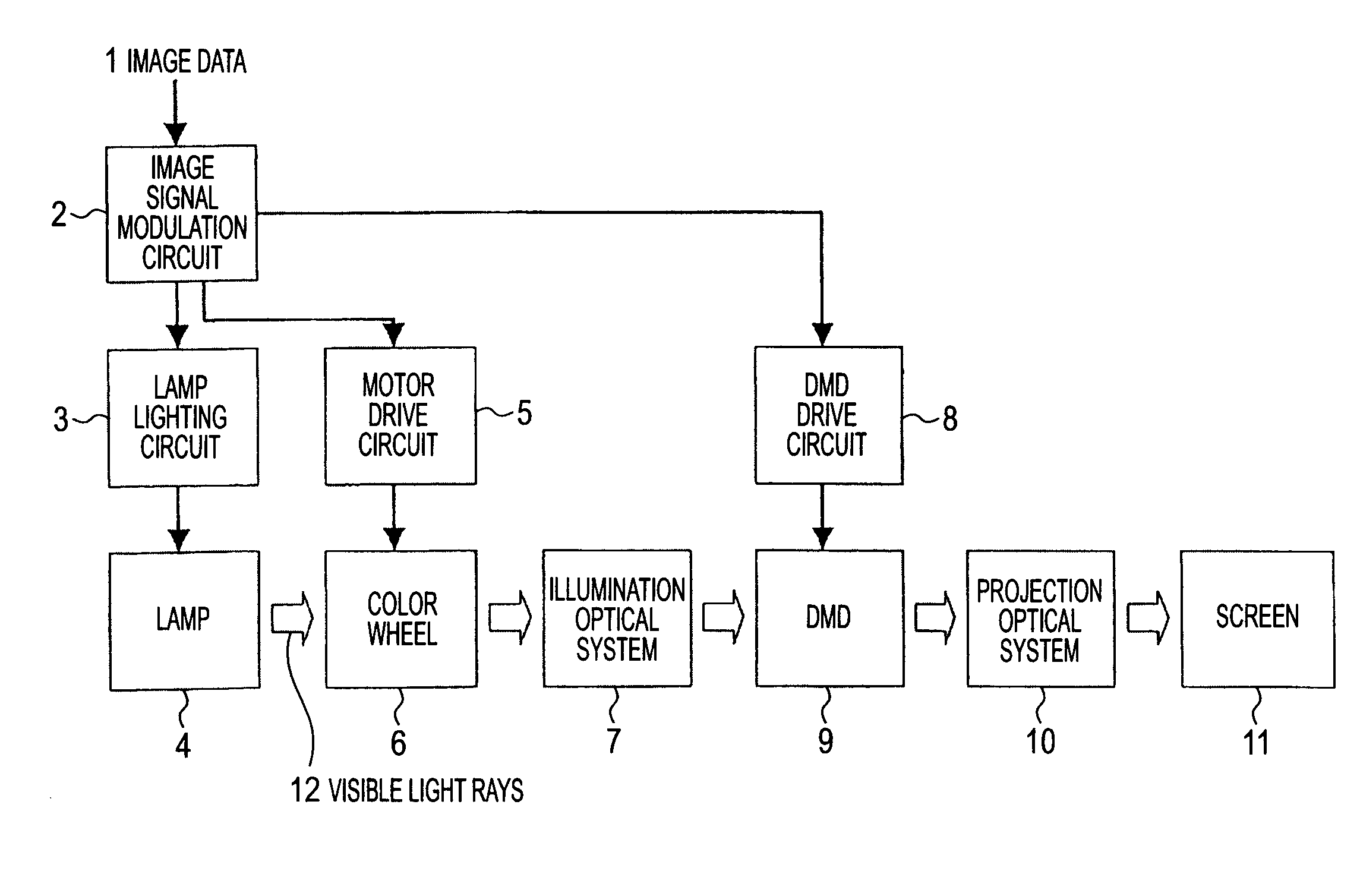
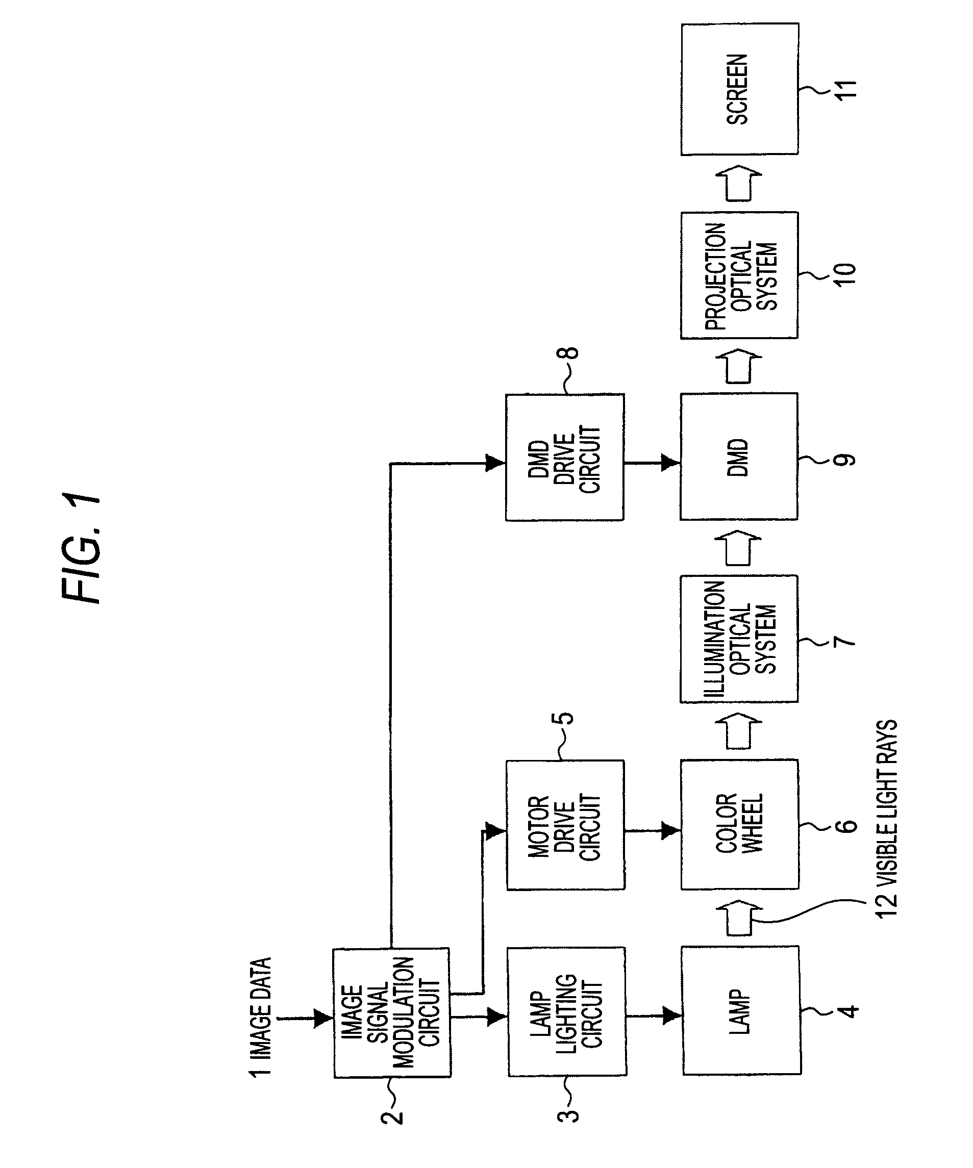
[0035]FIG. 1 is a system diagram of a projection display in a first exemplary embodiment of the present invention. In the present exemplary embodiment, a Digital Light Processing (DLP, registered trademark of Texas Instruments, Inc.) projection display will be described as the projection display. A DLP is a projection display that uses a DMD as a light modulating device.
[0036]In FIG. 1, an image signal modulation circuit 2 modulates inputted image data 1, sends the data to a DMD drive circuit 8, and also sends a synchronizing signal to a lamp lighting circuit 3 and a motor drive circuit 5.
[0037]The lamp lighting circuit 3 inputs a later-described specific power waveform to a lamp 4 serving as a light source to cause the lamp 4 to radiate visible light rays 12. The lamp 4 is, for example, an ultra high pressure mercury lamp, which is an HID lamp.
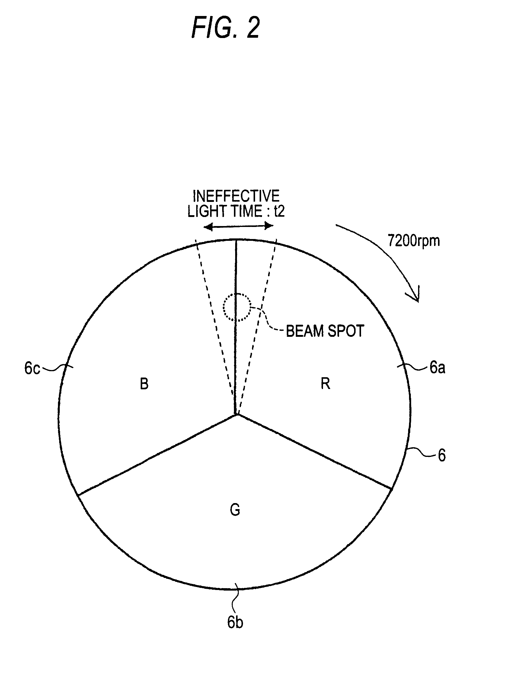
[0038]As shown in FIG. 2, a color wheel 6 is configured by a red transmission filter 6a, a green transmission filter 6b, and a blue transmis...
second exemplary embodiment
[0056]FIG. 5 shows a system configuration diagram of a projection display in a second exemplary embodiment of this invention, and the same reference numerals except 1 and 2 show portions that are the same as those in FIG. 1. What is different from the first exemplary embodiment is that here the projection display includes a luminance information detection circuit 20 that extracts luminance information from video information 1, and the luminance information detection circuit 20 outputs this luminance signal to a video signal modulation circuit 2 and the lamp lighting circuit 3. It will be noted that illustration of the motor drive circuit 5 that is driven in accordance with a synchronizing signal from the video signal modulation circuit 2 is omitted. The luminance information detection circuit 20 detects characteristics of luminance information on the basis of the video information 1 inputted from video information inputting means (not shown), digitalizes the characteristics as lumin...
third exemplary embodiment
[0070]In the second exemplary embodiment, the power P1 is adjusted under the condition that the average power is constant in order to keep the temperature of the lamp at a constant. Incidentally, as long as the temperature of the lamp is within the use temperature range of the lamp, the halogen cycle works appropriately even if the average power is changed somewhat, so the lifespan of the lamp is not adversely affected. In the lamp with a rating of 150 W described here, the average power that can be adjusted without going out of the use temperature range of the lamp was 110 W to 190 W. In the third exemplary embodiment, instead of the control described in the second exemplary embodiment that keeps the average power at a constant, means that adjusts the power P1 by changing the average power in a range where the halogen cycle of the lamp is appropriately conducted—that is, in the use temperature range of the lamp—will be described.
[0071]In FIG. 11, the bold solid line represents the ...
PUM
 Abstract
Description
Claims
Application Information
 - R&D
- Intellectual Property
- Life Sciences
- Materials
- Tech Scout
- Unparalleled Data Quality
- Higher Quality Content
- 60% Fewer Hallucinations
Browse by: Latest US Patents, China's latest patents, Technical Efficacy Thesaurus, Application Domain, Technology Topic, Popular Technical Reports.
© 2025 PatSnap. All rights reserved.Legal|Privacy policy|Modern Slavery Act Transparency Statement|Sitemap|About US| Contact US: help@patsnap.com


