Aryldiamine compound and organic electroluminescent element

a technology of organic electroluminescent elements and aryldiamine, which is applied in the field of aryldiamine compound and organic electroluminescent element, can solve the problems of low heat-resistant materials that decompose thermally, deteriorate devices, and insufficient electron blocking ability, and achieve excellent electron blocking properties, large hole mobility, and high hole injection properties.

Active Publication Date: 2020-07-23
HODOGOYA CHEMICAL CO LTD
View PDF0 Cites 0 Cited by
  • Summary
  • Abstract
  • Description
  • Claims
  • Application Information

AI Technical Summary

Benefits of technology

[0079]The aryldiamine compound of the invention is a novel compound and has (1) high hole injecting properties, (2) large hole mobility, (3) excellent electron blocking properties, (4) stability in thin film form, and (5) high heat resistance.
[0080]The organic EL device of the invention exhibits (6) high emission efficiency, (7) high power efficiency, (8) low onset voltage, (9) low driving voltage, and (10) long life.
[0081]The aryldiamine compound of the invention is suitably used as a material forming a hole transport layer or a hole injection layer of an organic EL device because of its higher hole injecting properties, higher hole mobility, higher electron blocking properties, and higher stability to electrons compared with conventional materials. An organic EL device having a hole transport layer or injection layer formed of the aryldiamine compound of the invention is capable of confining the generated excitons in the emitting layer, thereby providing an increased probability of hole-electron recombination to achieve high emission efficiency, and, at the same time, it drives at a lower voltage and has improved durability.
[0082]The aryldiamine compound of the invention is also suited for use as a material forming an electron blocking layer of an organic EL device because of its higher electron blocking ability, higher hole transporting properties, and higher stability in thin film form as compared with conventional materials. An organic EL device having an electron blocking layer formed of the aryldiamine compound of the invention achieves high emission efficiency, a low driving voltage, high current resistance, and a high maximum luminance.
[0083]The aryldiamine compound of the invention is also suitable as a material forming an emission layer of an organic EL device. The aryldiamine compound has higher hole transporting properties and a wider band gap than conventional materials. Therefore, the aryldiamine compound can be used as a host material which is doped with a fluorescent or phosphorescent guest material called a dopant to form an emission layer. An organic EL device having such an emission layer drives at a low voltage and achieves improved emission efficiency.
[0084]As described, the aryldiamine compound of the invention is useful as a material forming the hole injection layer, hole transport layer, electron blocking layer, or emission layer of an organic EL device, exhibiting large hole mobility, excellent electron blocking ability, stability in thin film form, and high heat resistance. The organic EL device of the invention has high emission efficiency and high power efficiency and, therefore, realizes reductions in driving voltage and onset voltage. It also enjoys high durability and long service life.

Problems solved by technology

Low heat-resistant materials decompose thermally, even in low temperatures, due to the heat generated on driving the device and eventually deteriorate.
Materials with low amorphous properties crystallize in a short time in thin film form, thereby deteriorating the device.
Some of the aromatic amine derivatives disclosed in patent literatures 1 and 2 exhibit hole mobility as high as 10−3 cm2 / Vs or higher but have insufficient electron blocking ability.
Organic EL devices using such aromatic amine derivatives allow part of electrons to pass through the emitting layer and, therefore, no improvement on emission efficiency is expected.
While devices using these compounds in the hole injection layer, hole transport layer, or electron blocking layer show improvements on heat resistance and emission efficiency, the effects obtained are still insufficient, and further reduction of driving voltage and higher emission efficiency have been demanded.

Method used


Image

  • Aryldiamine compound and organic electroluminescent element
  • Aryldiamine compound and organic electroluminescent element
  • Aryldiamine compound and organic electroluminescent element

Examples


example 1 — compound 1-2

Example 1—Compound 1-2

Synthesis of 1,2-bis[biphenyl-4-yl(9,9-dimethyl-9H-fluoren-2-yl)amino]benzene

[0208]In a reaction vessel purged with nitrogen were put 24.1 g of biphenyl-4-yl(9,9-dimethyl-9H-fluoren-2-yl)amine, 10.0 g of 1,2-diiodobenzene, 0.2 g of copper powder, 10.5 g of potassium carbonate, and 10 ml of dodecylbenzene. The mixture was stirred under reflux for 72 hours. The resulting reaction mixture was cooled, toluene added thereto to conduct extraction, and the extract filtered to remove insoluble solid, followed by concentration. The concentrate was purified by column chromatography using silica gel as stationary phase and toluene / n-heptane as eluent. The eluate was purified by recrystallization from a CH2Cl2 / acetone mixed solvent to give 15.7 g (yield: 65.0%) of Compound 1-2 as white powder.

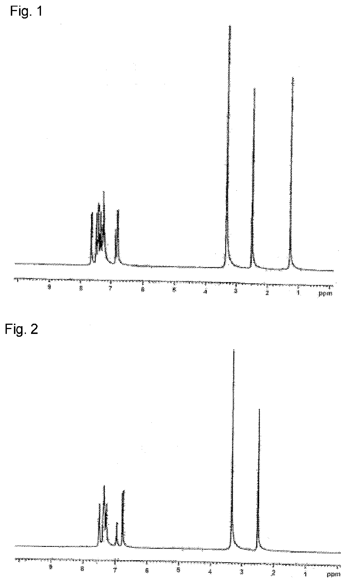
[0209]The white powder was analyzed by NMR analysis to identify the structure. As a result, the following 48 signals of hydrogen were observed in 1H-NMR (DMSO-d6). δ (ppm)=7.65 (4H), ...

example 2 — compound 2-1

Example 2—Compound 2-1

Synthesis of 2,2′-bis[di-(4-biphenyl)amino]biphenyl

[0210]In a reaction vessel purged with nitrogen were put 13.9 g of bis(4-biphenyl)amine, 8.0 g of 2,2′-diiodobiphenyl, 0.1 g of copper powder, 6.8 g of potassium carbonate, and 10 ml of dodecylbenzene. The mixture was stirred under reflux for 72 hours, the reaction mixture cooled, toluene added for extraction to remove insoluble matter, the extract filtered, and the filtrate concentrated. The concentrate was purified by recrystallization from a toluene / acetone mixed solvent to yield 10.9 g (70.0%) of Compound 2-1 as white powder.

[0211]The structure of the resulting white powder was identified by NMR analysis. As a result, the following 44 signals of hydrogen were detected in 1H-NMR (DMSO-d6). δ (ppm)=7.50 (8H), 7.39-7.30 (14H), 7.28-7.25 (10H), 6.96 (4H), and 6.76 (8H).

example 3 — compound 2-4

Example 3—Compound 2-4

Synthesis of 2,2′-bis[biphenyl-4-yl-(9,9-dimethyl-9H-fluoren-2-yl)amino]biphenyl

[0212]In a reaction vessel purged with nitrogen were put 15.7 g of biphenyl-4-yl(9,9-dimethyl-9H-fluoren-2-yl)amine, 8.0 g of 2,2′-diiodobiphenyl, 0.1 g of copper powder, 6.8 g of potassium carbonate, and 10 ml of dodecylbenzene. The mixture was stirred under reflux for one week, the reaction mixture cooled, toluene added for extraction to remove insoluble matter, the extract filtered, and the filtrate concentrated. The concentrate was purified by recrystallization from acetone to yield 12.7 g (73.8%) of Compound 2-4 as white powder.

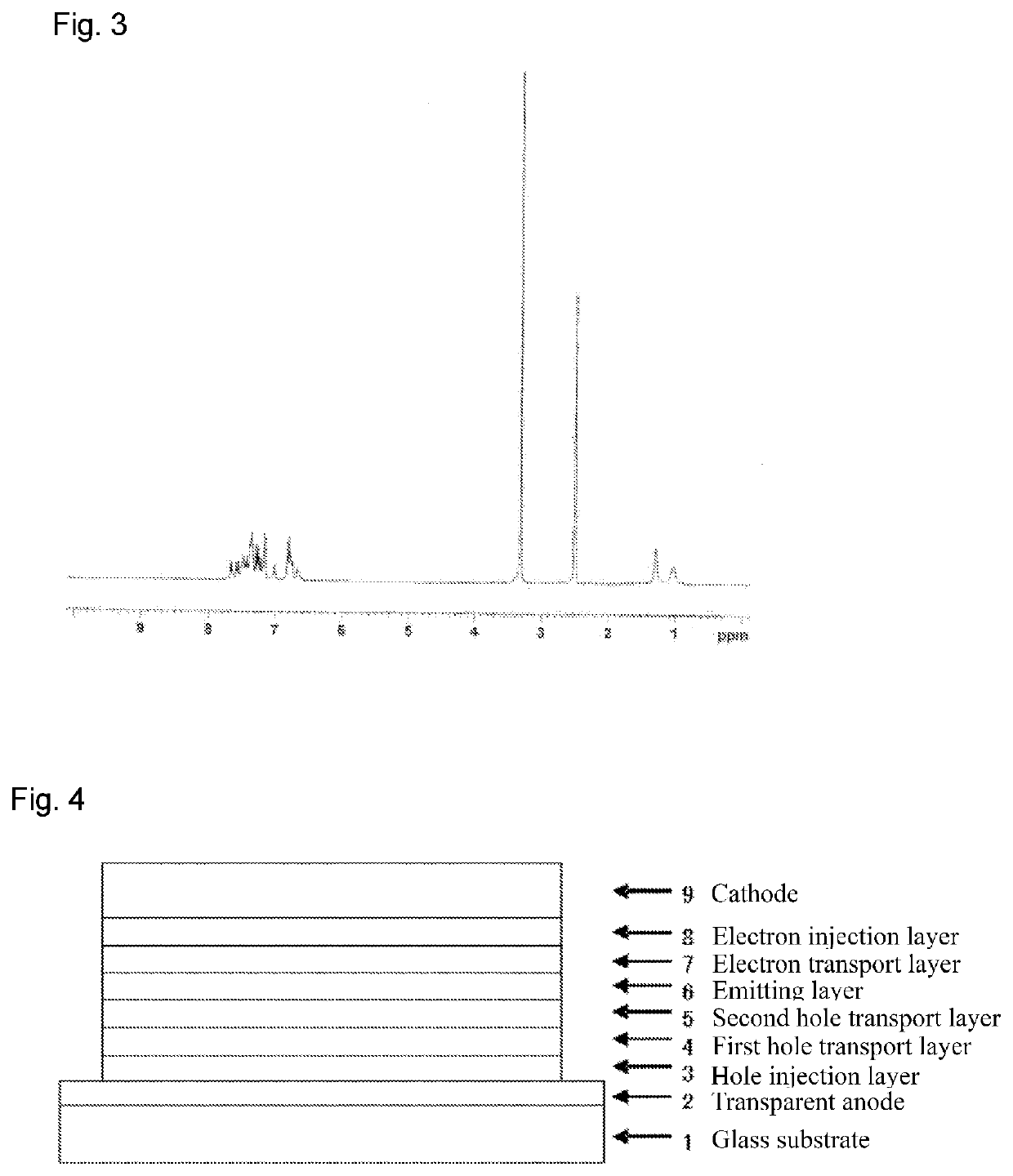
[0213]The structure of the resulting white powder was identified by NMR analysis. As a result, the following 52 signals of hydrogen were detected in 1H-NMR (DMSO-d6). δ (ppm)=7.66 (2H), 7.57 (2H), 7.48-7.14 (24H), 7.02 (2H), 6.83-6.64 (10H), 1.29 (6H), and 1.02 (6H).

[0214]The melting temperature and glass transition temperature of the compounds prepared ...


PUM

PropertyMeasurementUnit
voltageaaaaaaaaaa
luminanceaaaaaaaaaa
external quantum efficiencyaaaaaaaaaa

Abstract

An aryldiamine compound represented by formula (1) and an organic electroluminescent device including a pair of electrodes and at least one organic layer disposed therebetween wherein the at least one organic layer contains the aryldiamine compound. The aryldiamine compound is excellent in hole transporting properties, hole injection properties, electron blocking properties, stability in thin film form, and heat resistance. The organic electroluminescent device achieves high emission efficiency and power efficiency, drives at a low voltage, and, in particular, has a long life.

Description

TECHNICAL FIELD[0001]This invention relates to a compound suited for use in an organic electroluminescent device (hereinafter referred to as an organic EL device) and an organic EL device. More particularly, it relates to a specific aryldiamine compound and an organic EL device using the compound.BACKGROUND ART[0002]An organic EL device is self-luminescent, so that the organic EL device enables brighter, more visible, and clearer image display than liquid crystal devices and has therefore been studied extensively.[0003]C. W. Tang, et al. of Eastman Kodak developed a stacked device having a plurality of materials each performing its own role in 1987 and put an organic EL device using organic materials to practical use. An organic EL device is fabricated by stacking a fluorescent substance capable of transporting electrons and an organic substance capable of transporting holes. The opposite charges are injected to the emitting layer of the fluorescent substance to emit light, whereby ...

Claims


Application Information

Patent Timeline
Patent Type & Authority Applications(United States)
IPC IPC(8): C07C211/54C07C211/61H01L51/00
CPCH01L51/5056H01L51/006C07C211/61C07C211/54H01L51/5012C09K11/06C07C211/58C07C211/60C07C2603/18C07C2603/94C07C2603/42C07D307/91C07D333/76C07D409/14C07D209/88C09K2211/185C09K2211/1029C09K2211/1003H10K85/633H10K50/11H10K50/15H10K50/17C09K2211/1014C09K2211/1011
Inventor YAMAMOTO, TAKESHIKASE, KOUKIMOCHIDUKI, SHUNJI
Owner HODOGOYA CHEMICAL CO LTD
Why Eureka
Try Eureka