LED lighting device

a technology of led lighting and led streetlights, which is applied in the direction of energy-efficient lighting, sustainable buildings, and semiconductor lamp usage, etc., can solve the problems of consuming hundreds of watts of power for high-capacity led lighting devices including led streetlights, affecting the efficiency of lighting, so as to reduce energy, reduce heat generation, and prolong the life

Inactive Publication Date: 2015-01-29
CHEONIL
View PDF2 Cites 1 Cited by
  • Summary
  • Abstract
  • Description
  • Claims
  • Application Information

AI Technical Summary

Benefits of technology

[0028]As set forth above, in a light emitting diode (LED) lighting device according to exemplary embodiments of the present disclosure, an LED lamp module may be designed in consideration of an optimal driving environment of an LED lamp aiming at reducing energy and extending lifespan, thereby minimizing heat generated at the time of driving the LED lamp. In addition, the LED lamp module may be designed to provide the maximum luminous flux with respect to driving current, thereby maximally satisfying lifespan expectancy required by the LED lighting device.
[0029]In addition, a power supply provided with the LED lamp module may be configured in a high voltage low current form, thereby supplying sufficient power without the use of an electrolytic capacitor enormously affecting the lifespan of the converter. By extending the lifespan of the power supply, which is much shorter than that of the LED lamp module, maintenance cost of the LED lighting device may be reduced.
[0030]Furthermore, the efficiency of the power supply may be improved to 95% to 97% as compared with the 90% to 93% efficiency of the existing power supply by simplifying a circuit of the power supply used for the LED lamp module and removing the factors causing decline of efficiency, whereby luminous efficiency of the LED lighting device may be improved.
[0031]In addition, a defect generation rate of the product may be reduced by significantly simplifying constituent elements, and cost reduction of the power supply may lead to cost reduction of the LED lighting device.
[0032]Furthermore, according to exemplary embodiments of the present disclosure, the power supply may be designed to have a high voltage low current form, such that voltage drop does not occur even when the power supply and the LED lamp are distant from one another. Accordingly, the power supply may be installed inside a streetlight and a security light or in a lower portion (an inspection hole) of a light pole and may be used without additional manipulation,
[0033]In a case in which the high voltage low current power supply according to the exemplary embodiment of the present disclosure is applied to a light tower, it may have a great effect as compared to the streetlight.

Problems solved by technology

First, one factor is the luminous efficiency of LED elements constituting an LED lamp module of the LED lighting device and the heat-generation temperature, that is, a junction temperature (Tj° C.) at bases of the LED elements when the LED elements to which the luminous efficiency is applied are driven. In general, the lifespan of a converter is considerably shorter than that of an LED element. That is the lifespan of this LED module power supply (the converter) may be considered as the lifespan of the LED lighting device.
Second, the other factor is the lifespan of the power supply, that is, the converter, supplying driving power to the LED lamp module. The present invention relates to the configuration of the LED lamp module to which optimal driving conditions required by the LED elements are applied, and also relates to a heat radiation technology for reducing the junction temperature of the LED elements.
A high-capacity LED lighting device including an LED streetlight consumes hundreds watt of power, unlike interior lights.
With reference to FIG. 1, in a case in which current in the entirety of the LED lamp module is controlled by a single converter, when an abnormality occurs in any one group of LED elements and the LED elements fail to operate normally, current flowing in the abnormal group may be added to another group of LED elements, causing overcurrent.
However, this technology requires several to ten or more driver circuits in the case of an LED lighting device having a large capacity of hundreds of watts or greater.
For this reason, the circuit configuration may be complicated and the number of parts may increase, causing an increase in a defect generation rate.
This may result in a rise in price of the LED lighting device and a reduction in lifespan thereof.
In addition, in order to achieve cost reduction, the LED lighting device is often configured by allowing power consumption for a single LED package to be at least 70% of the maximum capacity of power available in the LED elements, resulting in increasing heat generated in the LED elements and shortening the lifespan.
In this case, as illustrated in FIGS. 4 and 5, the power supply should use an electrolytic capacitor for removing ripples included in the output voltage as the output current increases, resulting in shortening the lifespan of the product.
That is, the lifespan of the electrolytic capacitor used in the power supply may affect the lifespan of the LED lighting device.
In a case in which the low voltage high current power supply is used, voltage drop may occur according to a line length from the converter to the LED lamp module, and there is a limitation in a distance between the converter and the LED lamp module.
That is, a distance between the LED lighting device and the converter is necessarily limited to several meters, and thus, the power supply should be installed inside the lighting device.
This problem is not only limited to the streetlight, font also is serious in the case of a light tower having an LED lamp which is much higher than that of the streetlight.
In addition, since several to tens of lighting devices are installed in the light tower, unlike the streetlight, a defect generation rate of the power supply in the light tower is much higher as compared to the streetlight.
If a problem occurs under these circumstances, whenever the power supply is replaced, an expensive crane should be used.
This may lead to an increase in maintenance cost as well as difficulty in rapid reaction.
Therefore, it may be difficult to realize a basic purpose of LEDs, which is to achieve energy saving.
These elements may take up most of the cost of the power supply.
The above-described operation may lower the efficiency of the power supply.
In addition, a considerable amount of heat generated by the aforementioned elements may increase the defect rate of the power supply and shorten the lifespan of the product.

Method used


Image

  • LED lighting device
  • LED lighting device
  • LED lighting device

Examples


Embodiment Construction

[0047]Exemplary embodiments of the present disclosure will now be described in detail with reference to the accompanying drawings.

[0048]FIG. 8 illustrates the configuration of a lighting device according to an exemplary embodiment of the present disclosure.

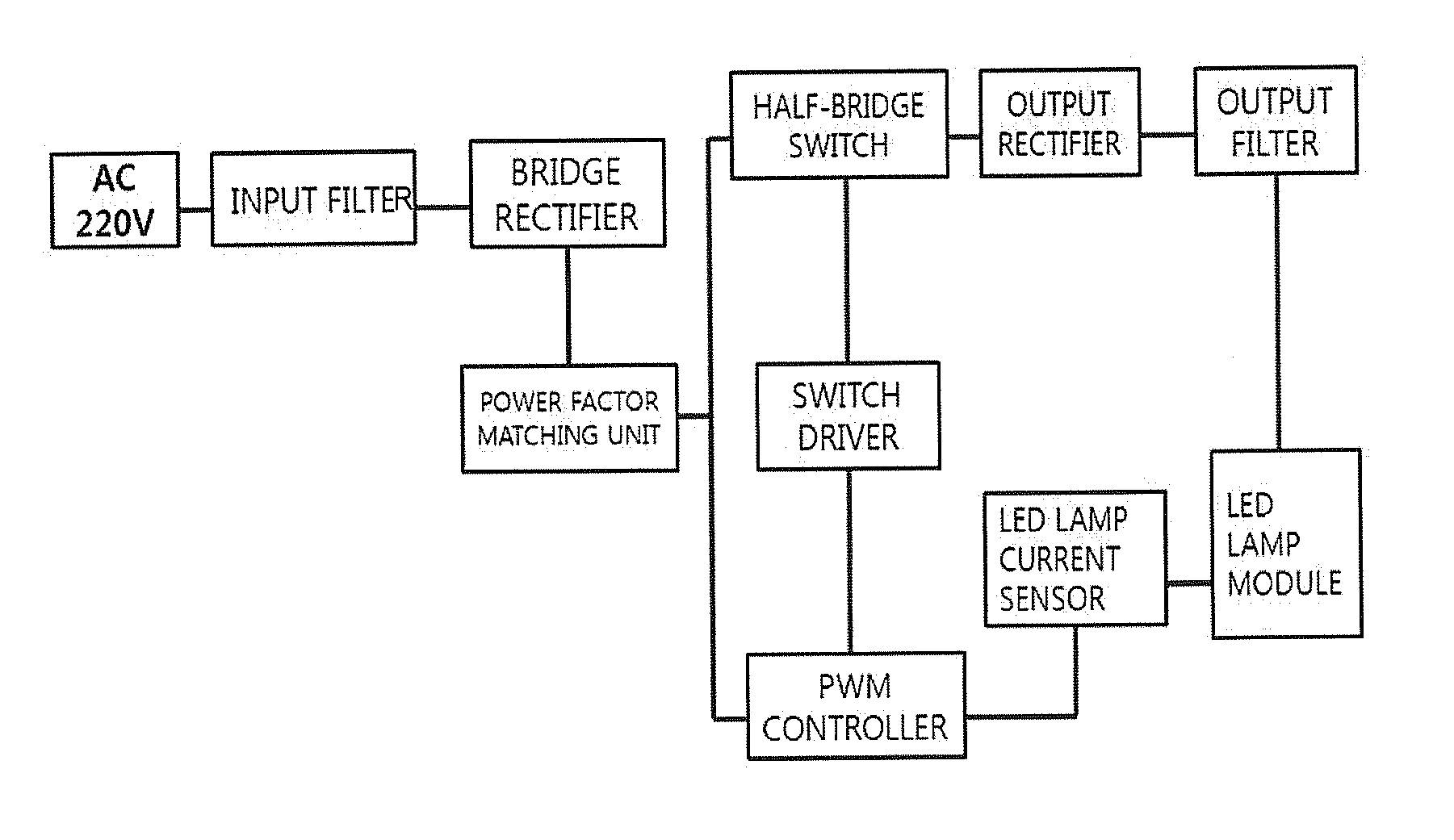
[0049]FIG. 9 is a block diagram of a power supply used in a lighting device according to an exemplary embodiment of the present disclosure, and FIG. 10 is a circuit diagram of a power supply used in a lighting device according to an exemplary embodiment of the present disclosure.

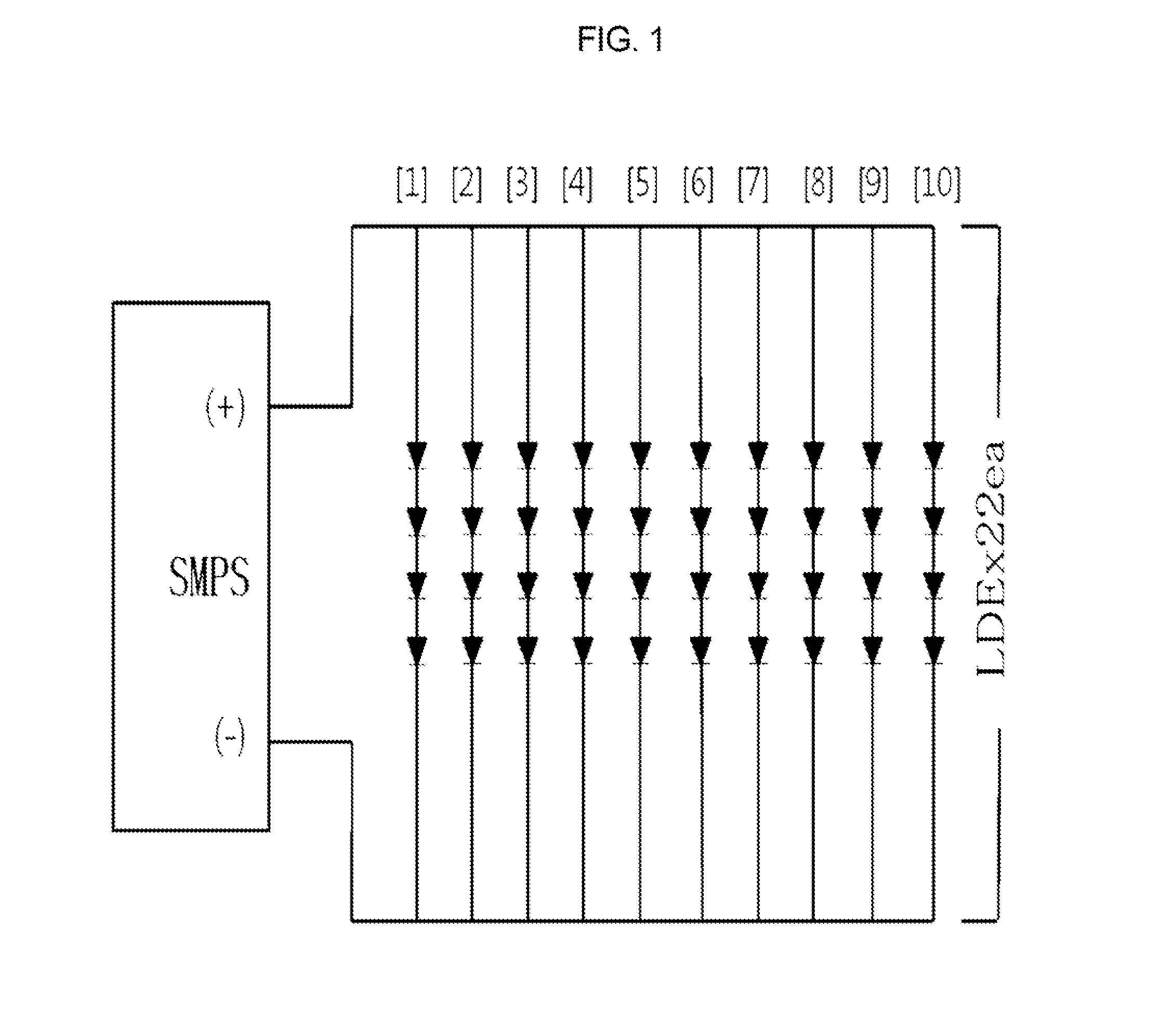
[0050]The lighting device according to the exemplary embodiment of the present disclosure may include at least one or more light emitting diode (LED) lamp modules and a switching mode power supply (SMPS) receiving electrical energy from an external power source to drive the LED lamp module.

[0051]At least one or more LED lamp modules according to this exemplary embodiment, as illustrated, may be arranged in series. In addition, the SMPS may convert AC power...


PUM


Abstract

The present disclosure relates to a technology or improving the efficiency of light emitting diode (LED) elements and extending the lifespan thereof, significantly reducing cost and improving efficiency of a power supply while supplying sufficient LED driving power to an LED lamp module without the use of an output-side electrolytic capacitor need in a converter, and extending the lifespan of the converter. Consequently, the present disclosure relates to a technology of reducing product cost and maintenance cost and extending the lifespan of an LED lighting device.

Description

TECHNICAL FIELD[0001]The present disclosure relates to a technology of extending lifespan of a light emitting diode (LED) module and a power supply, that is, a converter, constituting LED lighting devices including an LED streetlight.[0002]More specifically, the present disclosure relates to a technology of improving the efficiency of LED elements and extending the lifespan thereof, significantly reducing cost and improving efficiency of the power supply while supplying sufficient LED driving power to the LED lamp module without the use of an output-side electrolytic capacitor used in the converter, and extending the lifespan of the converter. Accordingly, the present disclosure relates to a technology of reducing product cost and maintenance cost and extending the lifespan of LED lighting devices.BACKGROUND ART [0003]In general, the following two factors may affect lifespan of a light emitting diode (LED) lighting device:[0004]First, one factor is the luminous efficiency of LED ele...

Claims


Application Information

Patent Timeline
Patent Type & Authority Applications(United States)
IPC IPC(8): H05B33/08H05B44/00
CPCH05B33/0815H05B33/0848H05B33/0821Y02B20/72H05B45/38Y02B20/30H05B45/40H05B45/39Y02B20/40H05B45/14
Inventor KIM, YOUNG HA
Owner CHEONIL
Why Eureka
Try Eureka