Luminescent photovoltaic generator and a waveguide for use in a photovoltaic generator

a photovoltaic generator and waveguide technology, applied in the direction of luminescent compositions, semiconductor devices, chemistry apparatus and processes, etc., can solve the problems of traditional panels nevertheless having their disadvantages, traditional panels not particularly well generating electricity, and luminescent photovoltaic generators

Inactive Publication Date: 2015-10-06
SIGNIFY HLDG BV +1
View PDF16 Cites 1 Cited by
  • Summary
  • Abstract
  • Description
  • Claims
  • Application Information

AI Technical Summary

Benefits of technology

[0008]It would be desirable to provide an alternative or an improved photovoltaic generator to those disclosed in the prior art. It may be improved, for example, in terms of efficiency and / or cost of manufacture.
[0011]Inorganic luminescent materials have been found to be preferable over organic luminescent materials since they do not tend to degrade over an extended period. In addition, they allow, when based on energy transfer and / or inorganic materials doped with rare-earth or transition metal ions, a large Stokes Shift without resulting in substantial thermal quenching of the luminescence. Moreover, certain embodiments of the present invention, as described below, may be used with easy-to-fabricate interference filters, particularly embodiments in which the wavelength difference between excitation wavelength and emission wavelength is large and the emission line width is small. In an embodiment, as described below, photo-stable quantum particles, such as quantum dots, quantum rods or core shell systems, can be used in or as the inorganic luminescent material. Re-absorption can be minimised by using quantum particles with indirect emission transitions, using small and large quantum particles. In the case in which energy is transferred from small to large quantum particles the large quantum particles are present in small amounts to prevent re-absorption by the large quantum particles.
[0018]In an embodiment, the inorganic luminescent material may comprises a plurality of types of first species that absorb at different wavelengths and a single type of second species that emits at a certain wavelength and the luminescent material is preferably a line emitter. This has been found to be advantageous in that it enables the material to have a broad absorption range, but emits substantially only at a single wavelength with a narrow band width. A plurality of different inorganic luminescent materials may be used in the device, the different materials having absorption over different wavelengths from one another, but having an emission peak that is the same or substantially the same (for example within about 20 nm) as one another, and preferably the inorganic luminescent materials are line emitters. As explained below, this allows relatively inexpensive interference filters that are selectively reflective only for the emitted wavelengths to be used, which saves on the cost of manufacture of the photovoltaic device.

Problems solved by technology

Such traditional panels nevertheless have their disadvantages.
Additionally, the traditional panels do not generate electricity particularly well if the incident light is diffuse, for example on a cloudy day.
Luminescent photovoltaic generators, although promising in theory, have yet to reach an efficiency that allows them to be used commercially.
It can be costly to provide light filters that reflect across a broad range of wavelengths.
Organic luminescent materials also suffer from degradation over an extended period, particularly from incident UV light.

Method used


Image

  • Luminescent photovoltaic generator and a waveguide for use in a photovoltaic generator
  • Luminescent photovoltaic generator and a waveguide for use in a photovoltaic generator
  • Luminescent photovoltaic generator and a waveguide for use in a photovoltaic generator

Examples


Embodiment Construction

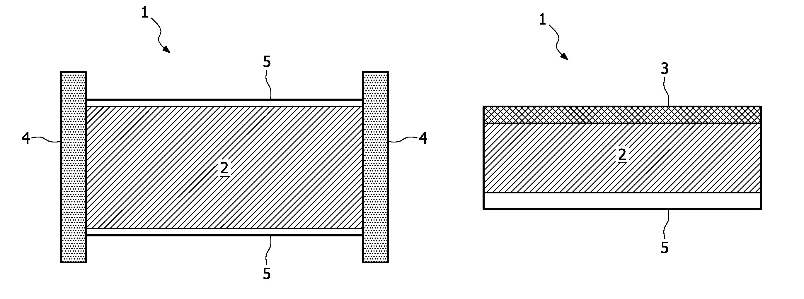
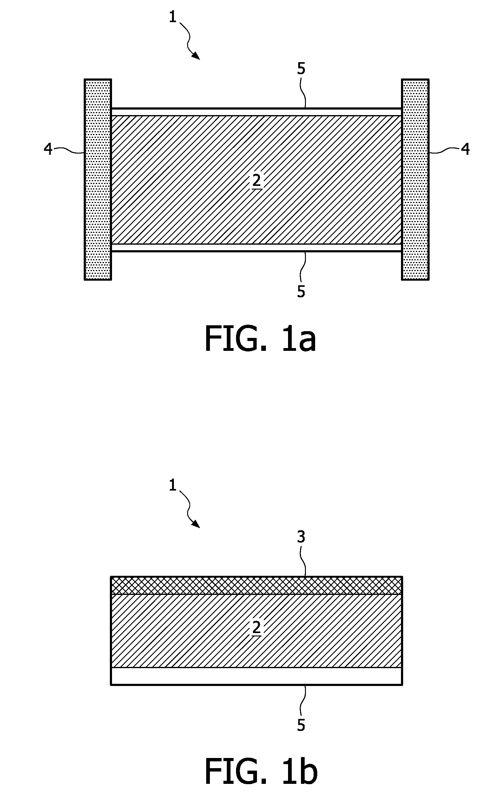
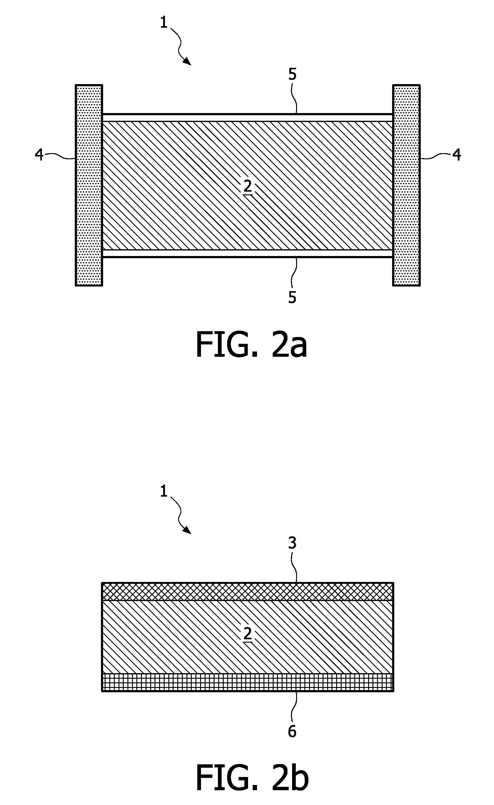
[0029]The present invention provides a waveguide for use in a photovoltaic generator, and a photovoltaic generator as described above.

Materials for Use in the Waveguide and Photovoltaic Cell

[0030]As described herein, the transparent matrix has (i) particles comprising an inorganic luminescent material dispersed therein and / or (ii) an inorganic luminescent material disposed at at least one side thereof. If the transparent matrix has particles comprising an inorganic luminescent material dispersed therein and an inorganic luminescent material disposed at at least one side thereof, the inorganic luminescent material of the particles and the material disposed at at least one side of the transparent matrix may be the same or different materials, and may be as described herein. The particles may comprise, consist essentially of or consist of the inorganic luminescent material. If the particles consists essentially of the inorganic luminescent material, preferably less than 5 wt %, more pr...


PUM

PropertyMeasurementUnit
widthaaaaaaaaaa
widthaaaaaaaaaa
wavelengthaaaaaaaaaa

Abstract

The present invention relates to a luminescent photovoltaic generator (1) and a waveguide for use in such a photovoltaic generator. The photovoltaic generator comprises a photovoltaic cell (4) and a waveguide comprising a transparent matrix (2) having particles of an inorganic luminescent material dispersed therein and / or an inorganic luminescent material disposed at at least one side thereof (6). The waveguide is associated with the photovoltaic cell (4), such that, in use, at least some of the light emitted from the luminescent material passes into the photovoltaic cell (4) to generate a voltage in the cell. In preferred embodiments, the inorganic luminescent material is a line emitter and the emission is due to a forbidden electronic transition within the material. The inorganic luminescent material may be selected from an inorganic phosphor, an inorganic fluorescent material and quantum dots, quantum rods and quantum core / shell systems. The photovoltaic generator (1) is an alternative to or an improvement upon known photovoltaic generators, which generally suffer from a lack of power yield per area.

Description

FIELD OF THE INVENTION[0001]The present invention relates to a luminescent photovoltaic generator and a waveguide for use in a photovoltaic generator.BACKGROUND OF THE INVENTION[0002]A photovoltaic generator is a device that generates electricity from light. There has been a constant effort over the past few years to increase the efficiency of photovoltaic generators. Traditional solar panels, having an array of solar cells, have become efficient to a point that commercialisation is now widespread. Such traditional panels nevertheless have their disadvantages. For example, to maximise power yield, they should be adapted to follow the sun as it crosses the sky. Additionally, the traditional panels do not generate electricity particularly well if the incident light is diffuse, for example on a cloudy day.[0003]In an effort to overcome some of the problems associated with traditional panels, research has recently been carried out into developing photovoltaic generators that can be used...

Claims


Application Information

Patent Timeline
Patent Type & Authority Patents(United States)
IPC IPC(8): C09K11/02H01L31/042H01L31/055C09K11/77H01L31/0216
CPCH01L31/055C09K11/02C09K11/7776C09K11/7792H01L31/02168Y02E10/52C09K11/77928
Inventor RONDA, CORNELIS REINDER M.DE BOER, DIRK KORNELIS GERHARDUS
Owner SIGNIFY HLDG BV
Why Eureka
Try Eureka