Single-power-key time delay state control PWM dimming circuit used for LED driver

A technology of LED driver and dimming circuit, applied in the direction of lamp circuit layout, electric light source, energy-saving control technology, etc., can solve the problems of large harmonics, harmonic pollution of power grid system, etc., achieve small size, wide dimming range, and high efficiency high effect

Inactive Publication Date: 2015-04-29
ZHEJIANG UNIV
View PDF8 Cites 5 Cited by
  • Summary
  • Abstract
  • Description
  • Claims
  • Application Information

AI Technical Summary

Problems solved by technology

At the same time, the biggest defect of this dimming method is that its chopping method will generate a large number of harmonics, which will cause harmonic pollution to the power grid system;

Method used


Image

  • Single-power-key time delay state control PWM dimming circuit used for LED driver
  • Single-power-key time delay state control PWM dimming circuit used for LED driver
  • Single-power-key time delay state control PWM dimming circuit used for LED driver

Examples


Embodiment Construction

[0028] In order to describe the present invention more specifically, the technical solution of the present invention will be described in detail below in conjunction with the accompanying drawings and specific embodiments.

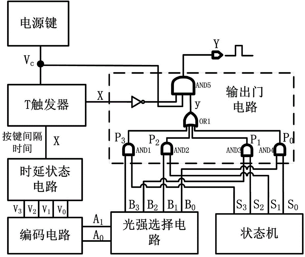
[0029] Such as figure 1 As shown, the PWM dimming circuit of the present invention includes: a power button, a T flip-flop, a delay state circuit, an encoding circuit, a light intensity selection circuit, a state machine and an output gate circuit; wherein:

[0030] The power key is used to generate the switch signal V c , and connect with T flip-flop and output gate circuit.

[0031] The T flip-flop is triggered by a rising edge, the T terminal is connected to a high level, and the clock signal is connected to the V generated by the power button. c Signal. The characteristic equation of T flip-flop is Q * =TQ'+T'Q, when the T terminal is connected to a high level, the characteristic equation becomes Q * =Q', so a special logic function of the T flip-...


PUM


Abstract

The invention discloses a single-power-key time delay state control PWM dimming circuit used for an LED driver. The circuit comprises a power key, a T trigger, a time delay state circuit, a coding circuit, a state machine, a light intensity selection circuit and an out-gate circuit. The single power key is used for controlling an LED lamp to be turned on and off, the brightness of the LED lamp can be selected according to the interval time spent in pressing a switch, and compared with a traditional LED lamp with multiple keys, the LED lamp is simpler and more intelligent, and the size of a product can be reduced. The single-power-key time delay state control PWM dimming circuit is combined with a currently-popular PWM brightness regulation method, multiple brightness degrees are provided so as to be selected by a user, the dimming circuit can be directly applied to the LED driver in a PWM brightness regulation scheme, efficiency is higher than that of a traditional LED driver adopting a linear dimming method, the dimming range is wider, the brightness of the LED lamp can be accurately controlled, a design thought is novel, and the diming circuit accords with the intelligent development trend of future products.

Description

technical field [0001] The invention belongs to the technical field of LED driving, and in particular relates to a PWM dimming circuit used for the time-delay state control of a single power supply key of an LED driver. Background technique [0002] In recent years, with the development of new materials and the improvement of technology, LED light source is called the fourth generation of new light source due to its high luminous efficiency, long life, small size, green and pollution-free, and is widely used in various lighting occasions Among them, such as LCD backlight, traffic lights, billboards, car lights and general home lighting. [0003] Compared with traditional light sources, LED has many unique characteristics and performance. LED is a low voltage DC device, its current and voltage characteristics are nonlinear, and the change of current will not only affect the luminous brightness, but also cause the change of color temperature, so the LED needs a special driver...

Claims


Application Information

Patent Timeline
Patent Type & Authority Applications(China)
IPC IPC(8): H05B37/02
CPCY02B20/40
Inventor 查振旭王曦陈祥杰陈泽华冯煊虞丹群王伟印
Owner ZHEJIANG UNIV
Why Eureka
Try Eureka