Power output apparatus and method of controlling the same

a technology of power output apparatus and power supply circuit, which is applied in the direction of electric devices, gas pressure propulsion mounting, driver interactions, etc., can solve the problems lowering the driving efficiency of the hybrid vehicle, and reducing the maximum electric current of the inverter circuit. , to achieve the effect of reducing the maximum load capacity of the motor and reducing the maximum electric curren

Inactive Publication Date: 2002-01-22
TOYOTA JIDOSHA KK
View PDF15 Cites 37 Cited by
  • Summary
  • Abstract
  • Description
  • Claims
  • Application Information

AI Technical Summary

Benefits of technology

is thus to provide a power output apparatus that reduces the maximum load capacity of a motor and decreases the maximum electr...

Problems solved by technology

This lowers the driving efficiency of the hybrid vehicle.
This arrangement further reduces the maximum load...

Method used


Image

  • Power output apparatus and method of controlling the same
  • Power output apparatus and method of controlling the same
  • Power output apparatus and method of controlling the same

Examples


Embodiment Construction

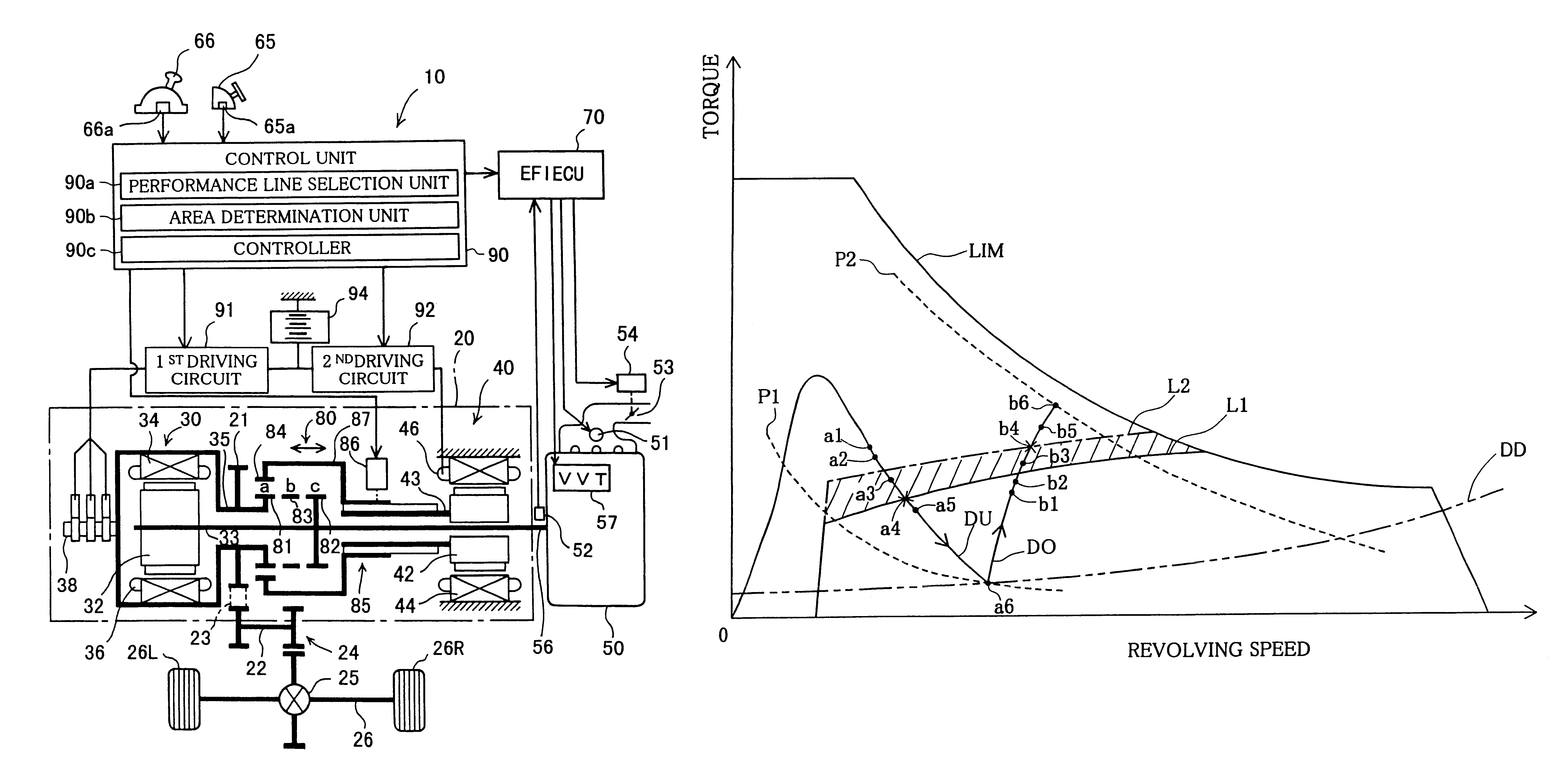
As described above, in the case where the working point of the outer rotor shaft 35 functioning as the drive shaft is present in the under drive area, the technique of the present invention mainly uses the WOT line L2, where the maximum torque of the engine 50 attains, as the performance line of the engine 50 that is used to determine the working point of the engine 50. This technique enables the greater torque to be output from the engine 50, compared with the conventional technique, when the working point of the outer rotor shaft 35 is present in the under drive area.

In the case where the working point of the outer rotor shaft 35 is present in the under drive area, the torque Ta of the assist motor 40 is expressed by the equation of Ta=Td-Te as shown by Equations (1) given above, where Td and Te respectively denote the torque of the outer rotor shaft 35 and the torque of the engine 50. This equation is rewritten to Td =Ta+Te. Namely the torque Td output from the outer rotor shaft ...


PUM


Abstract

In a power output apparatus of the present invention, a control unit sets a WOT (wide open throttle) line L2, where the maximum torque of an engine attains, as a boundary between an over drive area and an under drive area in the case where a rotor shaft of an assist motor is set in a state of over drive linkage. The control unit determines a target working point of an outer rotor shaft of a clutch motor, which functions as a drive shaft, based on an externally required output, and selects the WOT line L2 as a performance line of the engine in the case where the target working point of the outer rotor shaft is present in the under drive area. The control unit then sets a switching instruction flag, in order to change the state of linkage of the rotor shaft of the assist motor from the state of over drive linkage to a state of under drive linkage. This arrangement of the invention reduces the maximum load capacity of the assist motor and decreases the maximum electric current of an inverter circuit for driving the assist motor.

Description

1. Field of the InventionThe present invention relates to a power output apparatus including both an engine and a motor as the power source, as well as to a method of controlling such a power output apparatus. More specifically the invention pertains to a power output apparatus having a linkage mechanism that causes the motor to be linked with either one of an output shaft of the engine and a drive shaft.2. Description of the Related ArtOne of the recently proposed techniques is a hybrid vehicle with a power output apparatus mounted thereon, which includes both an engine and a motor as the power source (for example, JAPANESE PATENT LAID-OPEN GAZETTE No. 9-47094). A parallel hybrid vehicle is one of the hybrid vehicles. In the parallel hybrid vehicle, the power output apparatus mounted thereon causes part of the power output from the engine to be transmitted to a drive shaft via a power regulation unit and the residual part to be regenerated as electric power. The regenerated electri...

Claims


Application Information

Patent Timeline
IPC IPC(8): B60K6/00B60L11/12B60K6/04B60L11/02B60K6/20B60K6/26B60K6/365B60K6/387B60K17/04B60K6/40B60K6/448B60L50/15B60L50/16B60W10/02B60W10/04B60W10/06B60W10/08B60W10/10B60W10/11B60W10/12B60W20/00F02D29/00F02D29/02H02K7/10
CPCB60K6/365B60L7/14B60K6/448B60L11/123B60W10/02B60W10/06B60W10/08B60W20/00B60L11/005B60L11/14B60L11/1861B60L15/20B60K6/40B60K2006/262B60L2220/52Y02T10/56Y02T10/6217Y02T10/6243Y02T10/6286Y02T10/641Y02T10/7077Y02T10/92Y10S903/903Y10S903/951Y10S903/945Y10S903/946Y10S903/906Y10S903/91Y10S903/914Y02T10/7241Y02T10/7022Y02T10/7275Y02T10/642Y02T10/7044Y02T10/7005Y02T10/705B60L2210/40B60L2220/12B60L2220/14B60L2220/16B60L2240/12B60L2240/421B60L2240/423B60L2240/441B60L2240/443B60L2250/26B60L50/40B60L50/61B60L50/16Y02T10/40Y02T10/62Y02T10/64Y02T10/70Y02T10/72Y02T10/7072B60W30/18063Y02T10/84B60W20/11
Inventor KAWABATA, YASUTOMOMATSUHASHI, SHIGERUTAKAGI, NOBUYOSHIKANAMORI, AKIHIKOYAMADA, EIJI
Owner TOYOTA JIDOSHA KK
Why Eureka
Try Eureka