Roller thrust bearing cage and manufacturing method thereof

a technology of thrust bearings and cages, which is applied in the direction of shafts and bearings, rotary bearings, rolling contact bearings, etc., can solve the problems of increasing the contact speed between the projection and the end face of the roller, and affecting the production efficiency of the cage. , to achieve the effect of reducing the rotational torque and saving weigh

Inactive Publication Date: 2006-06-15
JTEKT CORP
View PDF6 Cites 10 Cited by
  • Summary
  • Abstract
  • Description
  • Claims
  • Application Information

AI Technical Summary

Benefits of technology

[0021] According to the invention, the drilling wear due to a contact between the inner face of the cage pocket and...

Problems solved by technology

However, in such the cage, due to limitation in machining shape of punching die for the cage pocket, the projections must extends over the thickness direction of the cage.
As a result, in such the structure, abnormal wear (drilling wear) can easily occur on the inner faces of the cage pocket.
However, if the cage is made of resin for saving weight, the thickness of the cage is increased in order to secure st...

Method used


Image

  • Roller thrust bearing cage and manufacturing method thereof
  • Roller thrust bearing cage and manufacturing method thereof
  • Roller thrust bearing cage and manufacturing method thereof

Examples


embodiment 1

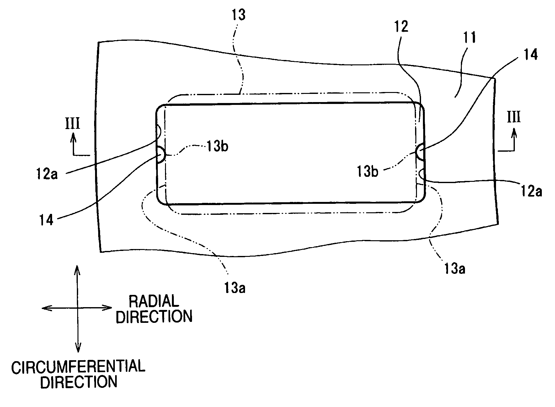
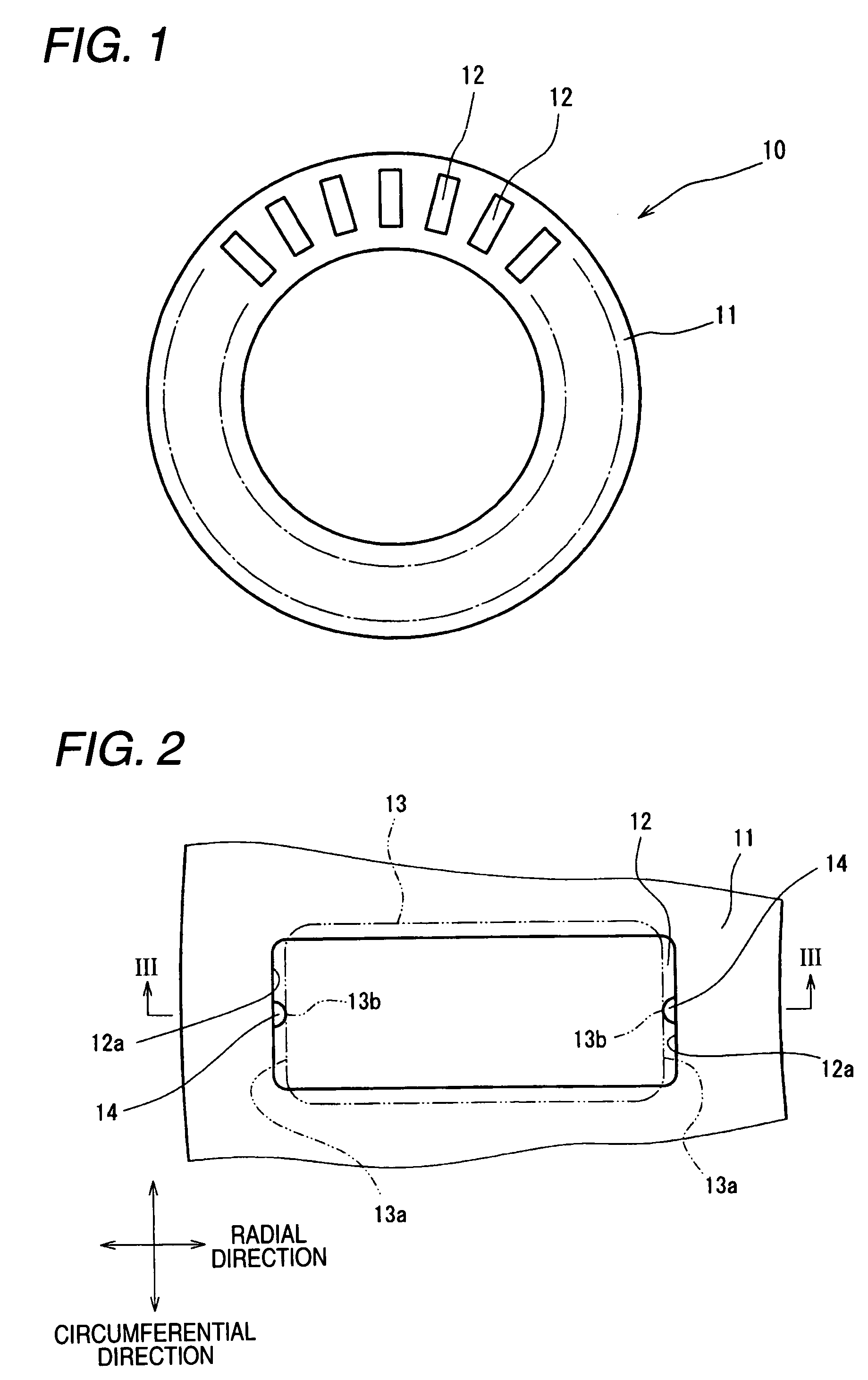
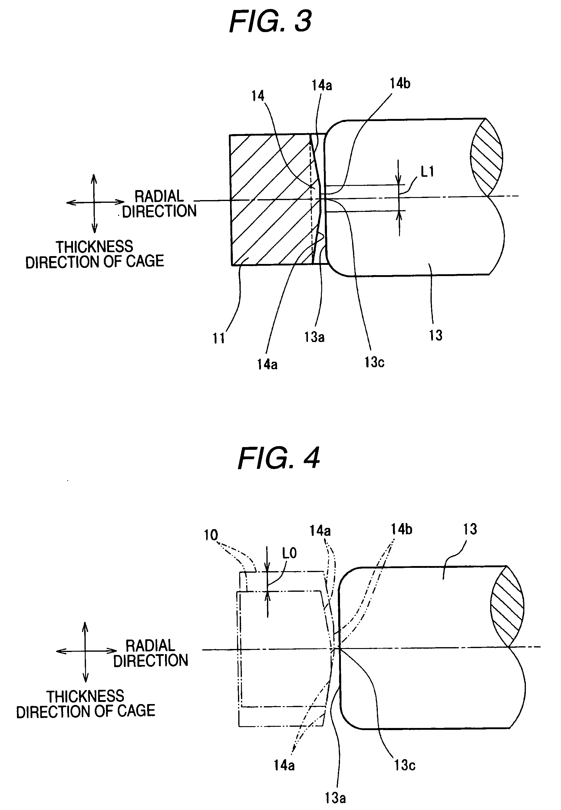
[0031]FIGS. 1 through 4 show the cage of Embodiment 1. FIG. 1 is a partial plan view showing a roller bearing cage, FIG. 2 is an enlarged plan view showing a vicinity of a cage pocket in FIG. 1, FIG. 3 is a sectional view taken on line III-III of FIG. 2, and FIG. 4 is an explanatory view showing a displaceable amount in a thickness direction of the cage.

[0032] A cage 10 according to Embodiment 1 as shown in FIG. 1 includes a ring plate 11 having an annular shape and formed of a resin, on which cage pockets 12 for retaining rollers are formed at plural positions along circumferential direction. The cage pockets 12 are opened and arranged in a radial manner around the center of the cage at a constant pitch of a predetermined angle. Each cage pocket 12 is formed in a rectangular shape elongated slightly in the radial direction from the center of the cage in accordance with the roller length, and houses a roller 13 having flat end races to obtain a large load capacity, Resin material f...

embodiment 2

[0039]FIGS. 5 through 8D show the cage according to Embodiment 2. FIG. 5 is a plan view showing a roller bearing cage, FIG. 6 is an enlarged plan view showing a vicinity of a cage pocket in FIG. 5, FIG. 7 is a sectional view taken on line VII-VII of FIG. 6, FIGS. 8A through 8C show a process forming chamfered portions of the cage of FIG. 5, and FIG. 8D shows a modification of the process forming the chamfered portions of the cage.

[0040] Referring to FIGS. 5 through 7, the cage 10 shown in these drawings includes a ring plate 11 formed from a metal like light alloy etc. or a steel plate by punching. The ring plate 11 has a W-shaped section in the radial direction and plurality of roller retaining cage pockets 12 are formed in a radial manner around the center of the cage 10. The cage pockets 12 are opened and formed simultaneously at the forming of the ring plate 11 by punching. Further, a roller retaining portion 12b is formed on a circumferential inner face 12a. On a radial inner ...


PUM

PropertyMeasurementUnit
Lengthaaaaaaaaaa
Thicknessaaaaaaaaaa
Shapeaaaaaaaaaa

Abstract

A cage includes cage pockets for retaining rollers at plural positions along a circumferential direction of an annular plate. A projection extending in thickness direction of the cage is formed at a central part in the circumferential direction on an inner face of the cage pocket to pivotally support the roller. The projection is provided with a chamfered portion (non-contact portion) formed by chamfering an edge in the thickness direction, and a flat portion (contact portion) that is brought into contact with an opposing central portion in the thickness direction on a roller end face of the roller seated in o the cage pocket. The flat portion has a flat length almost equivalent to a displaceable distance of the cage in the thickness direction thereof.

Description

BACKGROUND OF THE INVENTION [0001] 1. Field of the invention [0002] The present invention relates to roller bearing cages such as needle roller thrust bearings etc. More specifically, the invention relates to roller bearing cages such as needle roller thrust bearings etc. that are used in an automatic transmission of automobile, a compressor of a vehicle air conditioner or the like. [0003] 2. Description of the Related Art [0004] Trend for low fuel consumption of automobile in recent years has increased demands for further weight saving and further reduction of rotational torque to the roller thrust bearings that are mounted in various parts such as automatic transmission in the vehicle more and more. For weight saving, a cage made of resin has been proposed For reduction of rotational torque, there has been proposed a cage in which projections are formed at central parts in the circumferential direction on opposite inner faces of the cage pocket over the thickness direction of the ...

Claims


Application Information

Patent Timeline
IPC IPC(8): F16C33/48
CPCF16C19/30F16C33/4635Y10T29/49636F16C33/546Y10T29/49691F16C33/4682F16C33/543F16C19/305F16C33/48F16C33/54
Inventor TAKAMIZAWA, WATARU
Owner JTEKT CORP
Why Eureka
Try Eureka