Rolling bearing unit for supporting vehicle wheel

a technology for supporting vehicle wheels and rolling bearings, which is applied in the direction of hubs, mechanical devices, transportation and packaging, etc., can solve the problems of deterioration of traveling performance, troublesome appropriate control of these factors, and insufficient reduction of rolling resistance of rolling bearing units, so as to reduce the rotational torque of the whole rolling bearing unit, maintain the necessary sealing performance, and reduce the rotational torque

Inactive Publication Date: 2005-05-19
NSK LTD
View PDF5 Cites 0 Cited by
  • Summary
  • Abstract
  • Description
  • Claims
  • Application Information

AI Technical Summary

Benefits of technology

[0019] According to the rolling bearing unit of the present invention configured as described above, it is possible to sufficiently reduce the rotational torque while maintaining the necessary sealing performance. Namely, since the rotational resistance of the seal ring is lowered up to 0.2 N·m, it is possible to reduce the rotational torque of the whole rolling bearing unit.
[0020] On the other hand, since the rotational resistance of the above seal ring is at least 0.03 N·m, it is possible to secure necessary sealing performance (mainly, muddy water proof performance for preventing muddy water from entering).
[0021] Namely, from the result of the experiments conducted by the inventors of the present invention, it is found that the sealing performance can be verified in accordance with the value of the rotational resistance of the seal ring irrespective of the structure of the seal ring such as the profile and material thereof, as long as the number of the seal lips is two or three. It is also found that necessary sealing performance can be obtained by setting the rotational resistance of the above seal ring to at least 0.03 N·m.
[0022] Accordingly, in the case of the rolling bearing unit of the present invention in which the rotational resistance of the seal ring is from 0.03 to 0.2 N·m, it is understood that the rotational torque can be sufficiently reduced while maintaining the necessary sealing performance.

Problems solved by technology

However, since the rotational resistance of the seal ring is not necessarily low in the case of the conventional rolling bearing unit, the rolling resistance thereof cannot be sufficiently lowered.
This results in the deterioration of the traveling performance represented by acceleration performance and fuel consumption performance, and therefore improvement is desired in light of the recent energy saving requirement.
However, it is troublesome to appropriately control these factors in associating them with each other, so as to secure necessary seal performance, and also to reduce the rotational torque.

Method used


Image

  • Rolling bearing unit for supporting vehicle wheel
  • Rolling bearing unit for supporting vehicle wheel
  • Rolling bearing unit for supporting vehicle wheel

Examples


examples

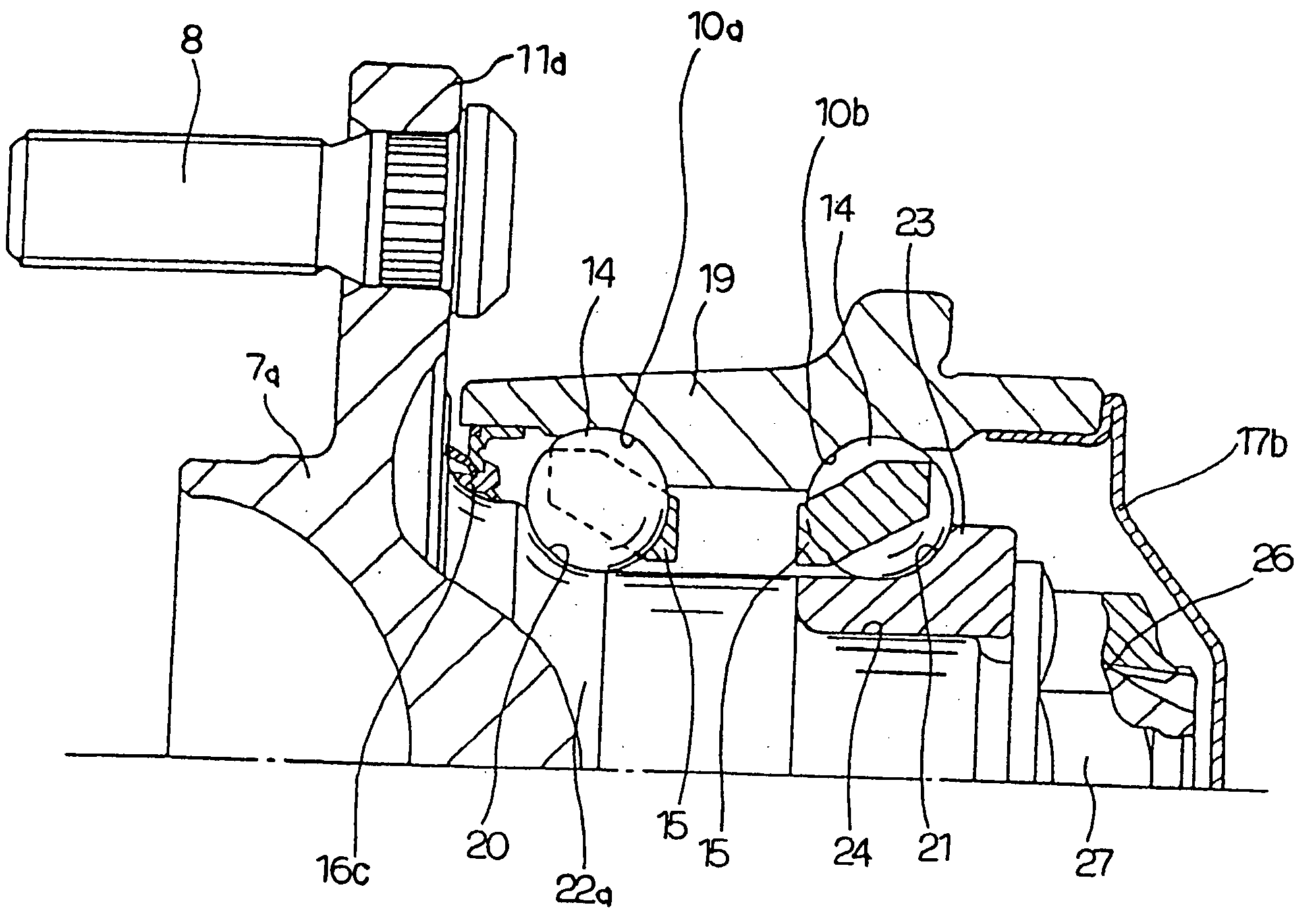
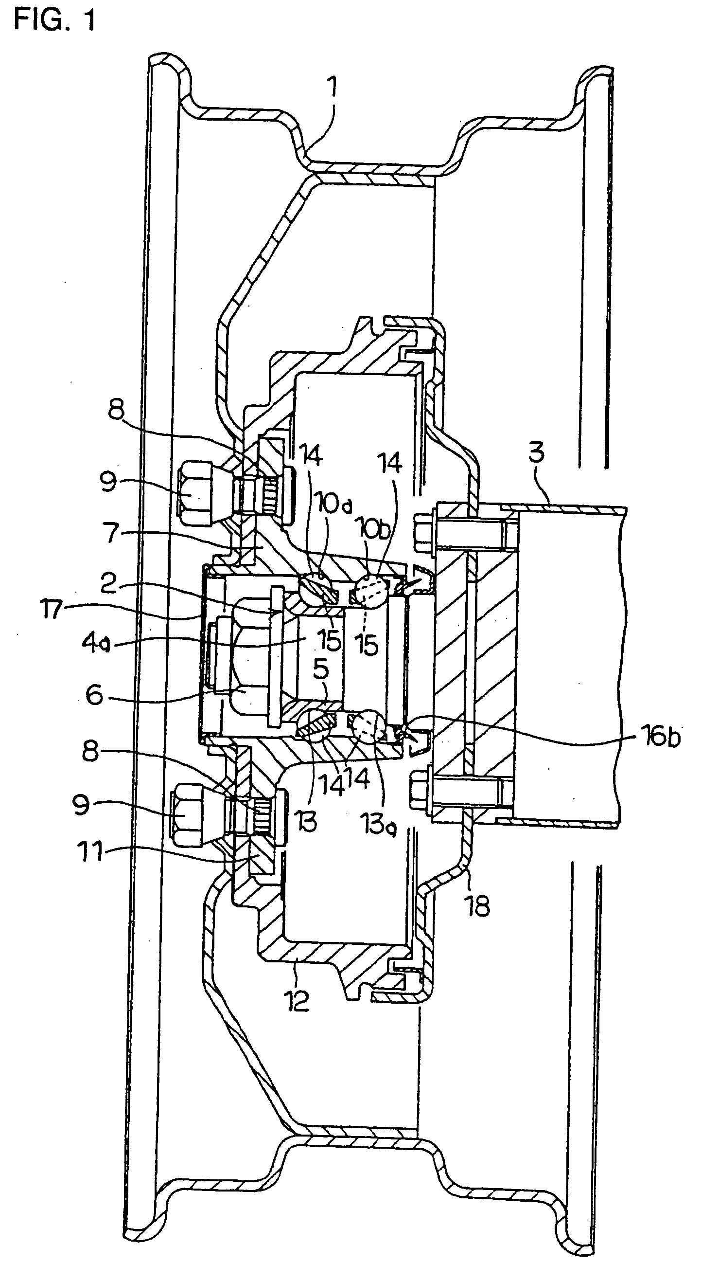
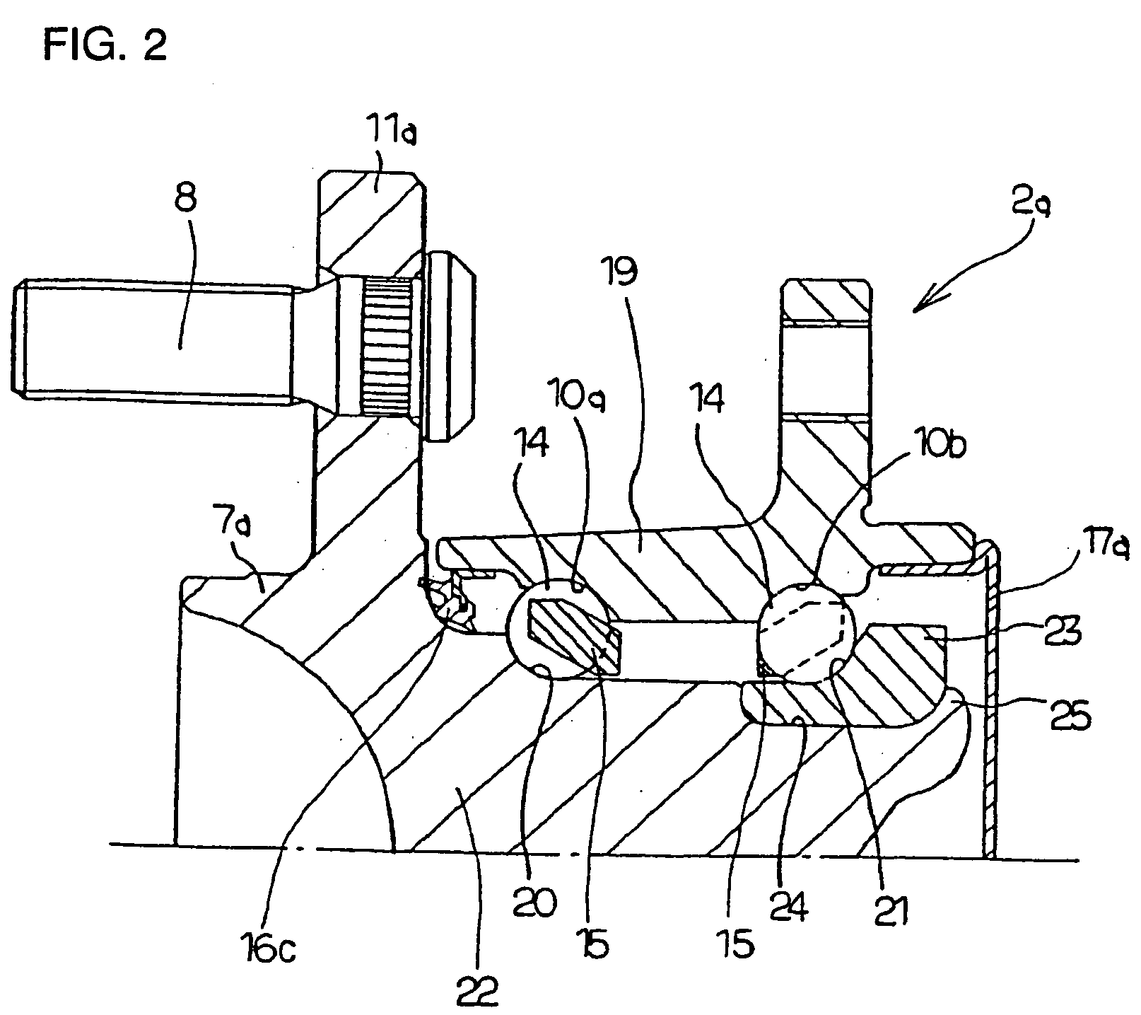
[0047] Next, the result of experiments conducted for confirming the advantages of the present invention will be explained. The experiments were conducted to investigate the relationship between the sealing performance and rotational resistance (seal torque) of a seal ring element by making use of 7 types of the seal ring as illustrated in FIGS. 4 to 10. The adjustment of the seal torque was performed by adjusting the interference (elastic deformation) of the seal lip, changing the elastic material, and adjusting the contact condition with the counterpart surface. For each of the above seven types of seal rings, six variations of seal rings respectively having seal torques of 0 to 0.22 N·m were prepared. Then, each seal ring was installed in the rolling bearing unit for supporting a vehicle wheel shown in FIG. 1 or FIG. 2 and subjected to a muddy water immersion test. The rolling bearing unit was lubricated by inserting a grease of 10 to 14 cSt (10 to 14×10−6 m2 / s) while the hub 7 or...


PUM


Abstract

In a rolling bearing unit for supporting a vehicle wheel, the traveling performance represented by acceleration performance and fuel consumption performance is improved by reducing the rotational torque of a hub rotating together with a wheel. An opening at an inside end of a space where balls are placed is closed by a cap, and another opening at an outside end thereof is sealed by a seal ring having three seal lips. The rotational resistance of the seal ring is limited within a range of 0.03 to 0.2 N·m resulting from the friction between the respective seal lips and the counterpart surfaces.

Description

FIELD OF THE INVENTION [0001] This invention relates to an improvement of a rolling bearing unit for rotatably supporting a vehicle wheel, particularly a non-driven wheel (a front wheel of an FR or RR vehicle, or a rear wheel of an FF vehicle), with reference to a suspension device of a motor vehicle. BACKGROUND OF THE INVENTION [0002] As a rolling bearing unit for supporting vehicle wheel, for example, JP Patent Unexamined Publication No. 2001-221243 discloses the structures as illustrated in FIGS. 11 and 12. In the structure of the first example shown in FIG. 11, a vehicle wheel 1 is rotatably supported by the rolling bearing unit 2 at an end portion of a shaft 3 as a part of a suspension device. Namely, inner rings 5 as stationary rings of the rolling bearing unit 2 are fitted and secured around a support shaft 4 fixed to the end portion of the shaft 3 by nuts 6. On the other hand, the wheel 1 is securely connected to a hub 7, which is a rotating ring of the rolling bearing unit ...

Claims


Application Information

Patent Timeline
Patent Type & Authority Applications(United States)
IPC IPC(8): B60B27/00F16C19/18F16C33/78F16J15/32
CPCF16C19/186F16C2326/02F16J15/3232F16C33/782F16J15/3264B60B27/02F16C33/723F16J15/324F16C19/185
Inventor SAKAMOTO, JUNSHI
Owner NSK LTD
Why Eureka
Try Eureka