Seat belt retractor and seat belt device

Inactive Publication Date: 2005-01-20
TAKATA CORPORATION
View PDF9 Cites 36 Cited by
  • Summary
  • Abstract
  • Description
  • Claims
  • Application Information

AI Technical Summary

Benefits of technology

[0024] When the high reduction ratio transmission mode is set, the low-speed and high-torque power transmission passage is established in the power transmission mechanism. Therefore, the rotational torque of the motor can be transmitted to the spool at a low speed and with high torque, thereby winding the belt with high torque for restraining the occupant. In the seat belt retractor, it is possible to obtain the two winding modes. Accordingly, it is possible to effectively perform flexible and simple control according to the performance required for winding up the seat belt without controlling the rotational torque of the motor.
[0025] The two power transmission passages are provided, so that the rotational torque of the motor is efficiently transmitted to the spool, thereby performing the two winding modes with limited power consumption. The seat belt is wound with the high torque for restraining the occupant through the low-speed and high-torque power transmission passage, there by reducing the rotational torque of the motor required as compared with a conventional device. Accordingly, it is possible to reduce the power consumption of the motor and allows the use of a smaller motor, thereby making the seat belt retractor compact. The seat belt retractor has the two winding modes to obtain a function of pre-tensioning the seat belt with the rotational torque of the motor.
[0026] In the seat belt retractor according to the second, third, fifth and sixth aspects of the invention, the power transmission mechanism is set in the low r

Problems solved by technology

Accordingly, the reduction ratio is limited so that it is difficult to flexibly and effectively obtain various rotational speeds of the spool and various belt winding torques on the spool.
However, it is difficult to control the motor through such a fine control system, and the power consumption increases.
However, when the rotational torque of the motor

Method used


Image

  • Seat belt retractor and seat belt device
  • Seat belt retractor and seat belt device
  • Seat belt retractor and seat belt device

Examples


Example

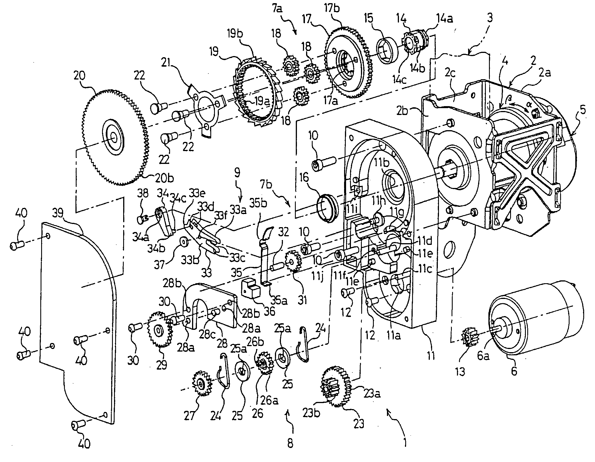
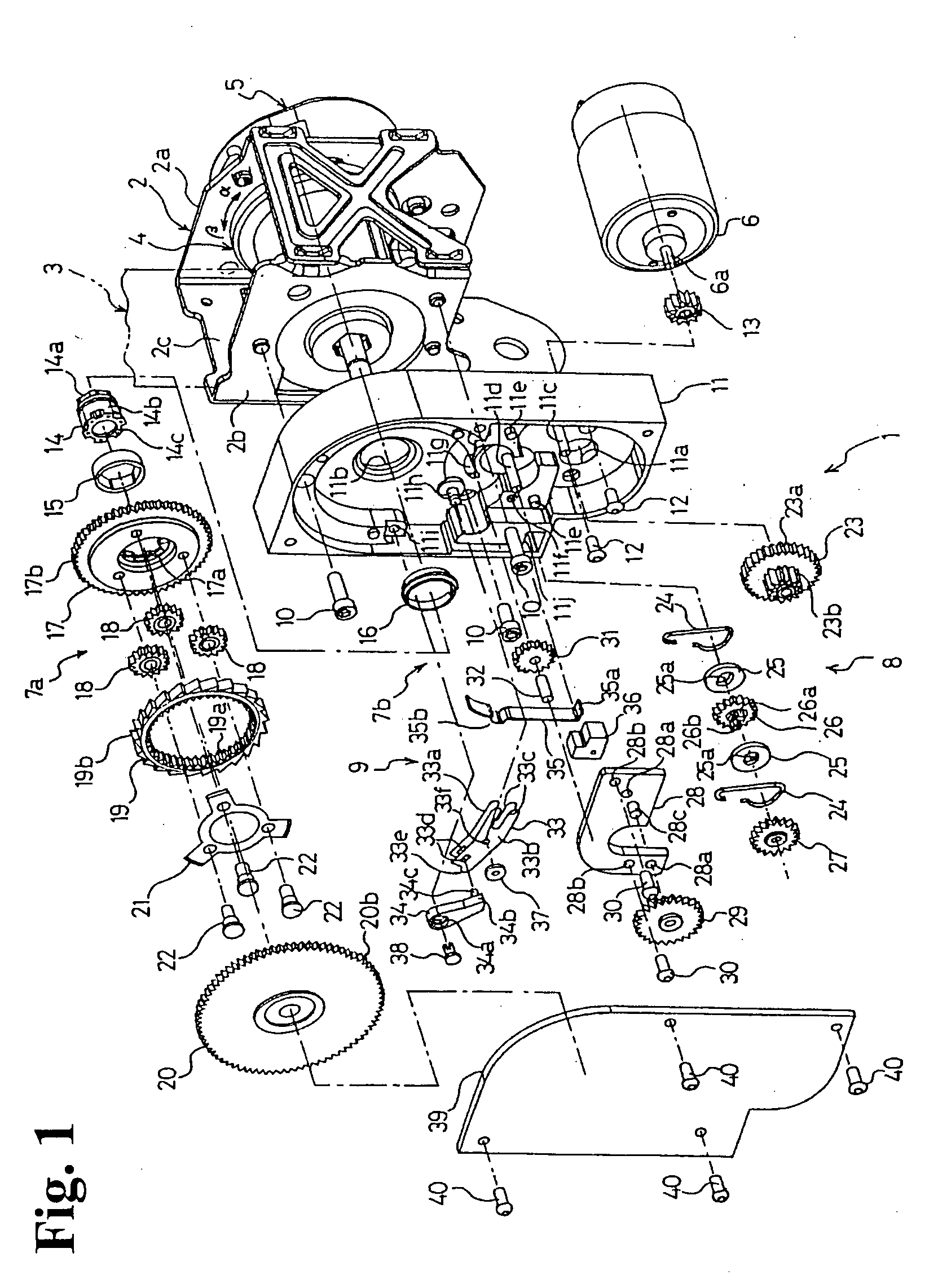
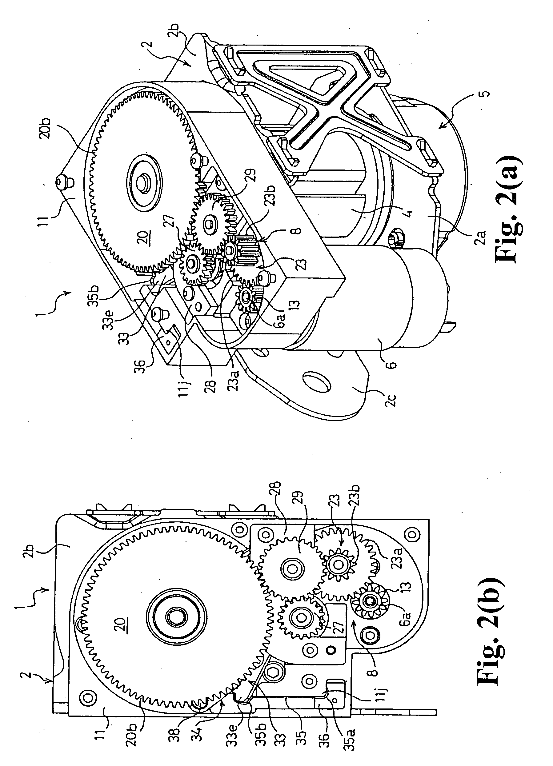
[0037] Hereinafter, embodiments of the present invention will be described with reference to the accompanying drawings. FIG. 1 is an exploded perspective view showing a seat belt retractor according to an embodiment of the present invention. FIGS. 2(a) and 2(b) are views showing the seat belt retractor shown in FIG. 1 in a state that a retainer cover is removed, wherein FIG. 2(a) is a perspective view thereof and FIG. 2(b) is a left side view thereof. In the following description, right and left represent right and the left in the drawings, and clockwise and counterclockwise represent clockwise and counterclockwise directions in the drawings unless stated otherwise.

[0038] As shown in FIG. 1, a seat belt retractor 1 mainly comprises a frame 2; a seat belt 3 for restrains an occupant as needed; a spool 4 for winding up the seat belt 3; a locking means 5 disposed on one side of the frame 2 to be actuated when deceleration larger than a predetermined value is generated upon a collision...


PUM


Abstract

A seat belt retractor includes a spool for winding up a seat belt; a motor for generating rotational torque to rotate the spool; and a power transmission mechanism for transmitting the rotational torque of the motor to the spool. The seat belt retractor winds the seat belt on the spool with the rotational torque of the motor. The power transmission mechanism has a low reduction ratio transmission mode in which the rotational torque of the motor is transmitted to the spool through a low reduction ratio mechanism, and a high reduction ratio transmission mode in which the rotational torque of the motor is transmitted to the spool through a high reduction ratio mechanism. The seat belt retractor further includes a power transmission mode switching mechanism for selecting between the low reduction ratio transmission mode and the high reduction ratio transmission mode.

Description

BACKGROUND OF THE INVENTION AND RELATED ART STATEMENT [0001] The present invention relates to a seat belt retractor installed in a vehicle such as an automobile for winding a seat belt onto a spool by a motor to restrain and protect an occupant and, more particularly, to a seat belt retractor for winding a seat belt efficiently by a motor using limited power. The present invention also relates to a seat belt device provided with the seat belt retractor. [0002] Conventionally, a seat belt device installed in a vehicle such as an automobile prevents an occupant from jumping out of a vehicle seat by restraining the occupant with a seat belt thereof, thereby protecting the occupant in the event of emergency such as a vehicle collision at which large deceleration is exerted on the vehicle. [0003] The seat belt device is provided with a seat belt retractor for winding up the seat belt. The seat belt retractor comprises urging means such as a spiral spring for urging a spool with the seat ...

Claims


Application Information

Patent Timeline
IPC IPC(8): B60R22/44B60R22/48B60R22/46
CPCB60R22/46B60R2022/4666B60R2022/4473B60R2022/444
Inventor INUZUKA, KOJITANAKA, KOJI
Owner TAKATA CORPORATION
Why Eureka
Try Eureka