Mechanical press

a mechanical press and press body technology, applied in the field of mechanical presses, can solve the problem of not as large inertia moment, and achieve the effect of reducing costs, increasing inertia moment, and slowing down

Inactive Publication Date: 2006-09-05
SCHULER PRESSEN GMBH & CO KG
View PDF8 Cites 41 Cited by
  • Summary
  • Abstract
  • Description
  • Claims
  • Application Information

AI Technical Summary

Benefits of technology

[0011]The servomotor or motors operate the plunger by way of a drive which includes an inertia moment. When needed, this inertia moment can be increased by an additional flywheel. Altogether, however, the inertia moment is not as large as it is in conventional presses wherein the flywheel stores enough energy to execute an operating stroke. Rather, it is so low that the servomotor or motors can accelerate the flywheel form standstill and can again slow it down when, in such a procedure, the plunger performs maximally one upward and one downward stroke. If the plunger travel distance is measured as a rotation of an eccenter shaft in degrees, the combined acceleration and deceleration travel distance is not more than 360°. This means that the drive torque of the servomotor or the total drive torque of all servomotors applied to the respective mass inertia moment is so large that the plunger can be accelerated to the desired value during a plunger travel distance of 180°. Also, the deceleration provided by the servomotors occurs over a distance of 180°. As a result, the press can be operated reversibly with variable operating strokes while the flywheel accommodates force peaks which result from the working of the workpieces and which therefore do not have to be generated solely by the servomotors. It is therefore possible to operate the presses in reversing operation with variable strokes wherein the flywheel ensures that force peaks which result from working the workpiece do not have to be accommodated alone by the servomotors.
[0012]The drive connections between each servomotor and the inertia mass only have to be designed for the maximum torque of the servomotors. This applies to the case where the servomotors are connected for example each by its own eccenter and connecting rod to the plunger as well as where the servomotors are connected to a common eccenter. If, for example, in the last case only one eccenter is provided which is operatively connected to a spur gear of larger diameter for rotation therewith, the pinion gears of several motors may be in engagement with such a large-diameter spur gear. Then the drive torque is transmitted to the spur gear by several pinions. As a result, the number of torque-transmitting teeth of the spur gear is substantially larger than with the use of a single strong servomotor whose pinion is in engagement with the spur gear. With the use of several servomotors jointly driving the spur gear, smaller and axially shorter teeth, that is narrower spur gears can be used which greatly reduces costs. Furthermore, there are different force transmission points distributed over the circumference of the spur gear which reduces also the load on the support structures. The disadvantages encountered with the omission of a large flywheel can therefore be compensated for, or even over-compensated. On the other hand, the advantage is obtained that any travel distance-time curve can be generated. It is particularly possible to extend the opening periods of a tool, that is the plunger can be held over an extended period in an upper position. In this way, the transfer of the workpiece is facilitated. In eccenter presses with constant speed, that is non-controllable drive motors wherein the eccenter movement cannot be slowed down during positioning of the work piece, a substantially larger stroke would be necessary for obtaining the same tool opening time at the same number of strokes.
[0014]In a particular embodiment, the slave motors are controlled each by its own torque controller so that it is ensured that the slave motors generate the same torque as the master. Although this solution requires more control expenses, it may be advantageous in view of the uniform torque distribution achieved thereby.
[0017]It is considered to be particularly advantageous if several servomotors drive a common spur gear which is connected to an eccenter. Such a drive is relatively inexpensive and sturdy and rigid. Since the force is transmitted by several pinions which are all in engagement with the spur gear, the whole force needed for the deformation of the workpiece can be transferred by way of this drive.

Problems solved by technology

Altogether, however, the inertia moment is not as large as it is in conventional presses wherein the flywheel stores enough energy to execute an operating stroke.

Method used


Image

  • Mechanical press
  • Mechanical press
  • Mechanical press

Examples


Embodiment Construction

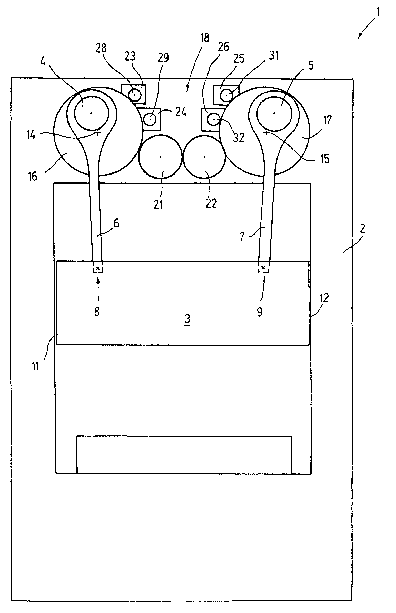
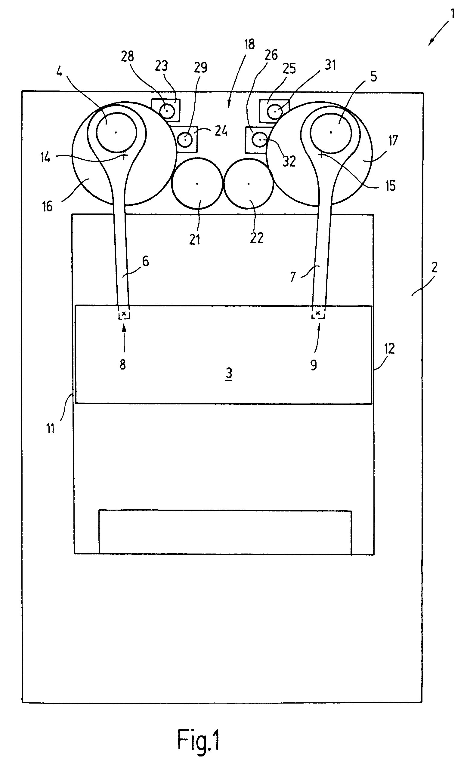
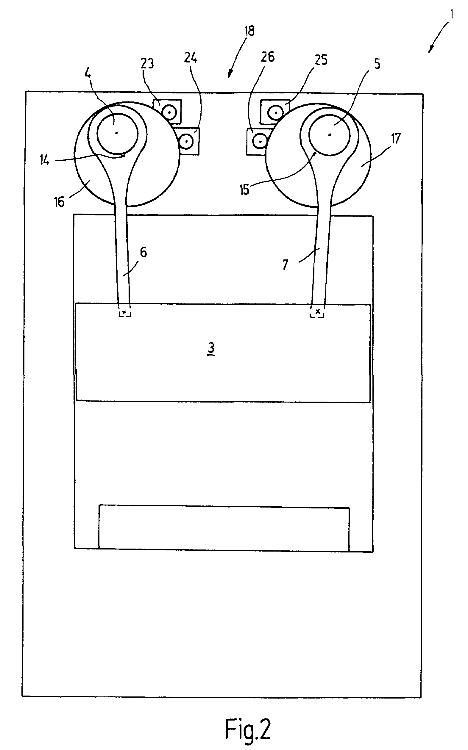
[0028]FIG. 1 shows a press 1 with a frame 2 on which a plunger 3 is supported so as to be movable up and down by two eccenters 4, 5, which are connected to the plunger 3 by connecting rods 6, 7. The connecting rods 6, 7 are pivotally connected to the plunger 3 at spaced locations 8, 9. Side guide structures 11, 12 guide the plunger 3 along the frame 3 for linear movement of the plunger 3.

[0029]The eccenters 4, 5 which may also be cranks are supported so as to be rotatable eccentrically about axes of rotation 14, 15 and are firmly connected to spur gears 16, 17, which are supported concentrically with the axes of rotation 14, 15. the spur gears 16, 17 are part of a drive 18, which includes also gears 21, 22, which couple the two spur gears 16, 17. The gears 21, 22 which are in engagement with each other and with the spur gears 16, 17 consequently provide for a drive connection between the spur gears 16, 17 and ensure their synchronism rotation in opposite directions.

[0030]The spur ge...


PUM


Abstract

In a press having a plunger supported so as to be movable linearly back and forth by drive means which include at least one servomotor in combination with a rotatably supported inertia structure connected for rotation with the servomotor, the inertia structure has an inertia moment which is small enough to permit reversal of the servomotor within a stroke length of the plunger so that the stroke of the plunger is adjustable under the control of a control device connected to the servomotor for controlling its operation.

Description

BACKGROUND OF THE INVENTION[0001]The invention relates to a mechanical press for example for shaping metal sheets but also for forming massive parts. The press includes a plunger which is movable back and forth by a drive arrangement.[0002]Mechanical presses generally include a main drive with a shaft which is driven by one or several electric motors and which drives one or more eccenters which are directly connected to a plunger by a connecting rod or indirectly by a bell crank. The main shaft is connected to a flywheel which compensates for load variations and which makes the rotation of the main shaft more uniform.[0003]With such presses, the distance-time curve which the plunger follows is determined by the eccenter drive or possibly a bell crank drive. Even if the stroke of the plunger is adjustable the basic distance-time characteristic cannot be changed.[0004]Therefore presses have been proposed wherein the eccenter driving the plunger is driven by a servomotor.[0005]Such an ...

Claims


Application Information

Patent Timeline
Patent Type & Authority Patents(United States)
IPC IPC(8): G05B11/32B30B1/26B30B15/14G05B19/408
CPCB30B1/266B30B15/148G05B2219/41264
Inventor BEYER, JOACHIMHOFELE, HANSLAUKE, ANDREAS
Owner SCHULER PRESSEN GMBH & CO KG
Why Eureka
Try Eureka