Omni-wheel based drive mechanism

a technology of drive mechanism and omni-wheel, which is applied in the direction of endless track vehicles, vehicle components, vehicles, etc., can solve the problems of inability to move smoothly when being used indoors, affecting the driving efficiency of the drive roller, and narrow paths available in the house for the robots. achieve good driving

Inactive Publication Date: 2010-09-30
CHUNG HUA UNIVERSITY
View PDF0 Cites 39 Cited by
  • Summary
  • Abstract
  • Description
  • Claims
  • Application Information

AI Technical Summary

Benefits of technology

[0008]A primary object of the present invention is to provide an omni-wheel based drive mechanism that enables good driving of a spherical wheel with a plurality of omni wheels and vice versa.
[0011]With the technical means adopted by the present invention, the omni wheels can keep rotating in a rotating direction following the rolling direction of the spherical wheel without the risk of becoming stuck due to different included angles between the omni wheels and the -spherical wheel. Therefore, it is not necessary to produce the spherical wheel with a low-friction material to ensure the slipping between the spherical wheel and the omni wheels. Meanwhile, under guiding by the omni wheels, the spherical wheel can roll in a smooth manner to ensure high driving efficiency.
[0012]With respect to the driving efficiency of the present invention, since the spherical wheel is driven to roll by paired omni wheels, enhanced and balanced driving force can be obtained. In addition, there is a relatively large contact area between the omni wheels and the spherical wheel to ensure sufficient friction force and accordingly, reduced possibility of undesired slipping between them. Further, the driving forces produced by the omni wheels are always tangent to the spherical wheel and can therefore produce the largest torque while driving the spherical wheel. Moreover, during driving, it is a plurality of guide rollers mounted on the circumferential wheel faces of the omni wheels that sequentially contact with the spherical wheel. Since the wheel faces of the omni wheels are not in direct and close contact with the spherical wheel, the problem of accumulated dust between the omni wheels and the spherical wheel can be avoided.
[0013]With the present invention, both the structural weight and the structural load of the whole omni-wheel based drive mechanism will be transformed into a contact force between the omni wheels and the spherical wheel. The contact force will increase proportionally with the increasing structural weight or the structural load to reduce the possibility of undesired slipping. Further, the magnitude of the contact force is in a fixed proportion to the space between two omni wheels in one pair. The smaller the space between the paired omni wheels is, the larger the contact force between the omni wheels and the spherical wheel will be. Therefore, it is possible to apply the drive mechanism of the present invention to different loading conditions by adjusting the space between the paired omni wheels.

Problems solved by technology

Thus, while a robot with more wheels can be accepted for use outdoors, it fails to move smoothly when being used indoors, such as in a house, because the paths available in the house for the robot are usually narrow and complicated.
The high friction of the spherical wheel would, however, cause difficulty in slipping between the spherical wheel and the drive roller and the idler roller and accordingly, have adverse influence on the driving efficiency of the drive roller.
In conclusion, there are still many problems being encountered with in designing the drive mechanism for a robot.
A robot with three or more wheels can stably maintain balance, but it requires a relatively large space to turn around and is therefore not suitable for using indoors.
And, in the one-wheeled robot, the required friction between the spherical wheel and the drive rollers and idler rollers is different from the required friction between the spherical wheel and the floor, and it is impossible for the spherical wheel to have a high friction and a low friction at the same time.
As a result, the one-wheeled robot usually has relatively low driving efficiency.

Method used


Image

  • Omni-wheel based drive mechanism
  • Omni-wheel based drive mechanism
  • Omni-wheel based drive mechanism

Examples


first embodiment

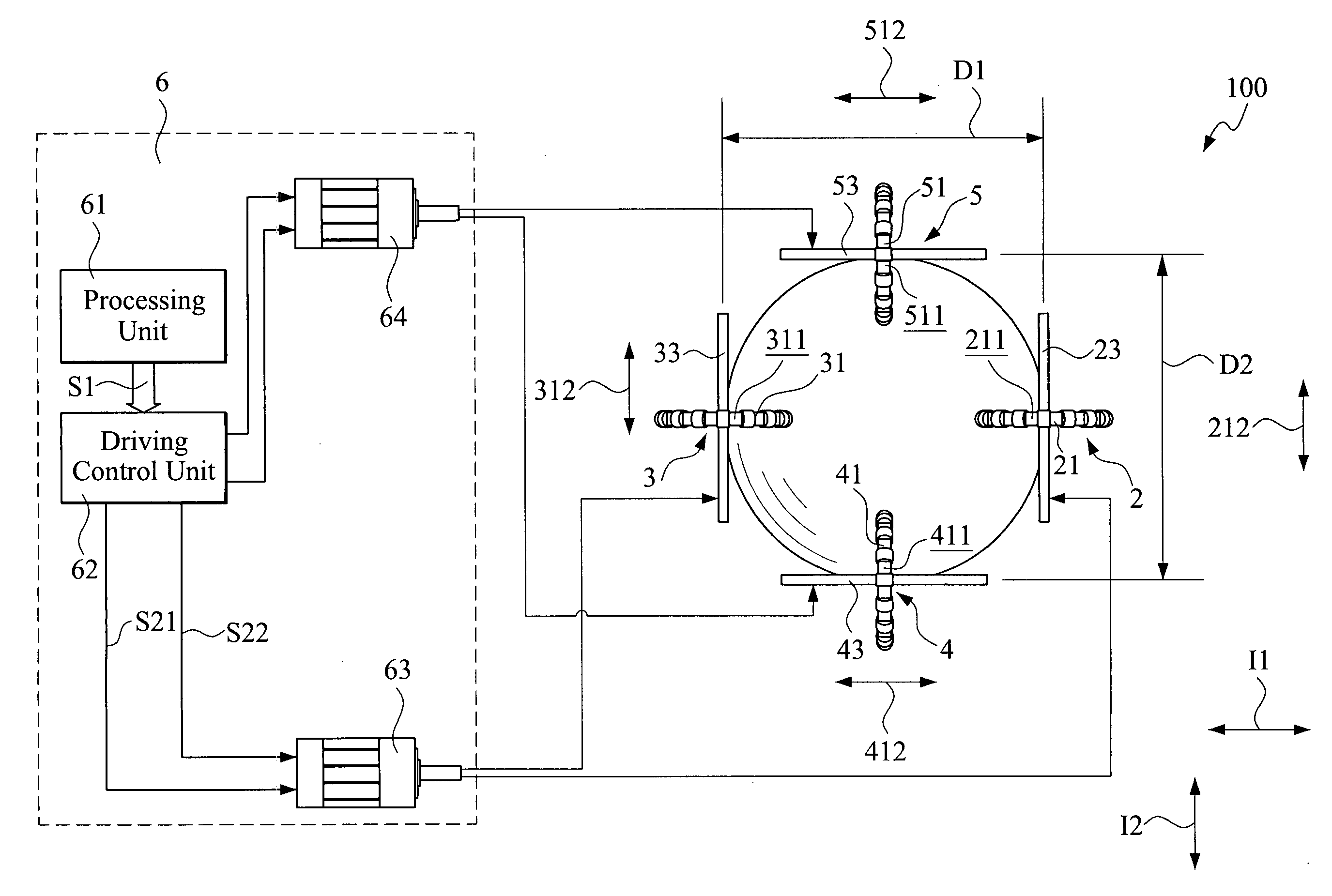
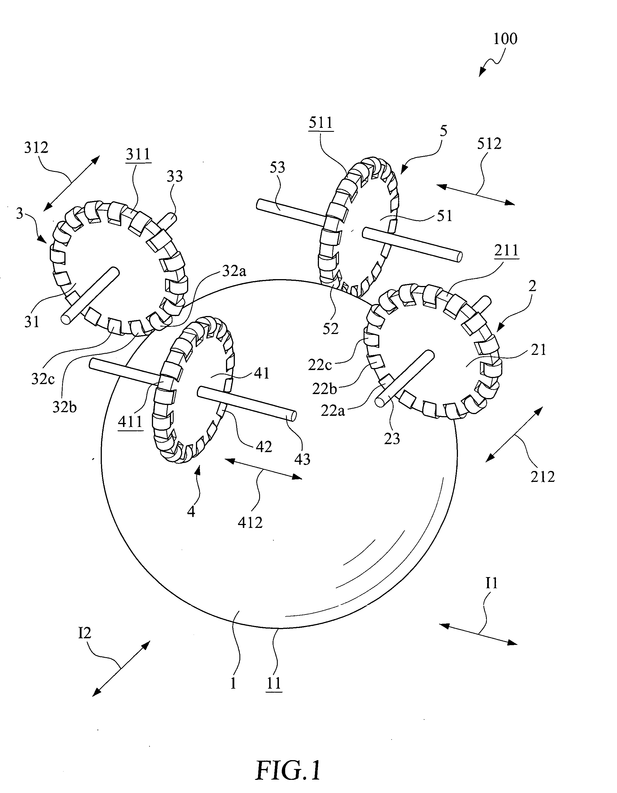
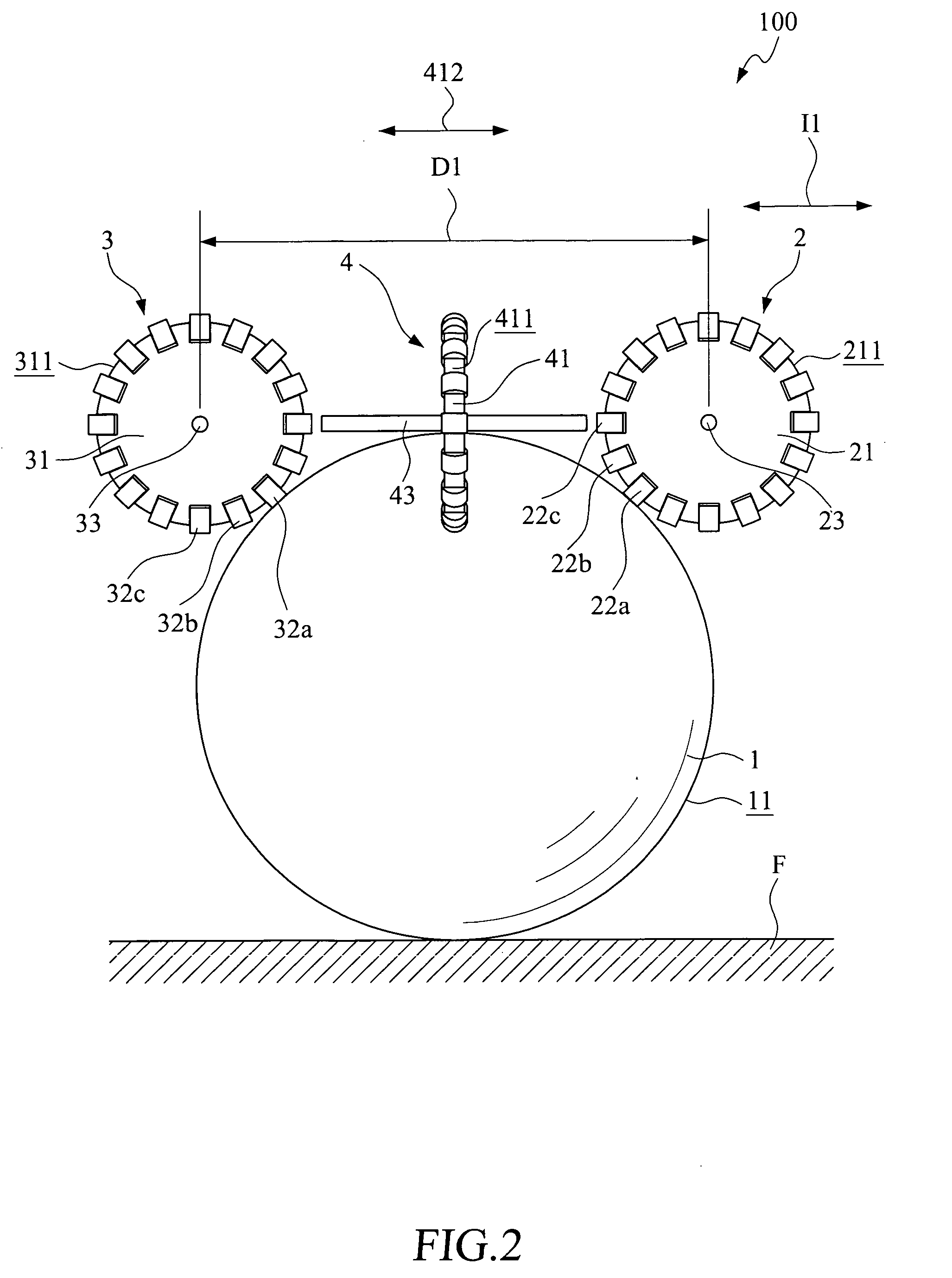
[0031]In the first embodiment, the first direction I1 and the second direction I2 are orthogonal to each other. The spherical wheel 1 is positioned among the first omni wheels 2, 3 and the second omni wheels 4, 5. Of course, the first and the second direction I1, I2 are not necessarily orthogonal to each other, but can contain other different angles between them, depending on actual design and intended use of the drive mechanism.

[0032]The control circuit 6 includes a processing unit 61, a driving control unit 62, a first driving unit 63, and a second driving unit 64. The driving control unit 62 is electrically connected to the processing unit 61; and both of the first and the second driving unit 63, 64 are electrically connected to the driving control unit 62. The first driving unit 63 is used to drive the first omni wheels 2, 3, to rotate and the second driving unit 64 is used to drive the second omni wheels 4, 5 to rotate. In the first embodiment, the first and the second driving ...

third embodiment

[0039]FIG. 7 is a side view showing an omni-wheel based drive mechanism 100a according to the present invention. FIG. 8 is a fragmentary and enlarged side view of a link for a chain used in the omni-wheel based drive mechanism. The omni-wheel based drive mechanism 100a is generally structurally similar to the previous embodiments, and includes a plurality of omni wheels 8. Each of the omni wheels 8 includes a main wheel 81, a plurality of guide rollers 82a, 82b, and a drive axle 83.

[0040]The third embodiment is different from the previous embodiments in that the main wheel 81 of the omni wheel 8 includes a driving wheel 811, a guide rail 812, and a driving belt. The driving belt is wound around the driving wheel 811 and the guide rail 812. The guide rollers 82a, 82b are rotatably mounted on and spaced along the driving belt. When the driving wheel 811 brings the driving belt to move, the guide rollers 82a, 82b on the driving belt sequentially contact with the spherical face 11 of th...


PUM


Abstract

An omni-wheel based driving mechanism includes a spherical wheel, a pair of first omni wheels, and a pair of second omni wheels. The first omni wheels are arranged at two sides of the spherical wheel to space from each other by a predetermined distance in a first direction, so that the spherical wheel is rollably positioned between the first omni wheels. The second omni wheels are arranged at another two sides of the spherical wheel to space from each other by a predetermined distance in a second direction, so that the spherical wheel is rollably positioned between the second omni wheels. Therefore, a good driving efficiency can be obtained between the spherical wheel and the-first omni wheels and the second omni wheels.

Description

FIELD OF THE INVENTION[0001]The present invention relates to a drive mechanism, and more particularly to an omni-wheel based drive mechanism.BACKGROUND OF THE INVENTION[0002]With the constantly developed scientific technologies, the use of robots has become highly popular among different industrial and commercial fields. There are many different types of drive mechanisms designed for robots. One of the most common robots is a wheeled robot provided with one or more wheels. Usually, for the purpose of keeping static and dynamic balance, the conventional wheeled robots have three or more wheels each. In the case of having a large number of wheels, the robot usually requires a relatively large turning radius to move to another direction. Thus, while a robot with more wheels can be accepted for use outdoors, it fails to move smoothly when being used indoors, such as in a house, because the paths available in the house for the robot are usually narrow and complicated.[0003]To enable the ...

Claims


Application Information

Patent Timeline
Patent Type & Authority Applications(United States)
IPC IPC(8): B62D57/00
CPCB60B19/14B60B19/003B62D57/00
Inventor WU, CHIA-WENHWANG, CHI-KUANG
Owner CHUNG HUA UNIVERSITY
Why Eureka
Try Eureka