
Vehicle and vehicle control method

a technology of vehicle control and control method, applied in the field of vehicles, can solve the problems of poor controllability and width modulation control, and achieve the effect of suppressing the instability of voltage applied to the motor during the battery-less travel control

Active Publication Date: 2014-09-25
TOYOTA JIDOSHA KK +1
View PDF8 Cites 38 Cited by
  • Summary
  • Abstract
  • Description
  • Claims
  • Application Information

AI Technical Summary

Benefits of technology

The invention aims to solve the problem of instability in voltage during battery-less travel control in a vehicle. The vehicle includes a generator that generates power, a battery that can be connected to the motor and generator, and a control apparatus that drives the motor through pulse width modulation control when speed is low and rectangular control when speed is high. The control apparatus also performs battery-less travel control when the battery fails. By implementing a speed limitation and limiting torque of the engine or motor, instability in voltage can be suppressed during battery-less travel control.

Problems solved by technology

The control apparatus drives the motor through pulse width modulation control when a vehicle speed is lower than a threshold and drives the motor through rectangular control in which the motor can output a larger torque but poor controllability in comparison with the pulse width modulation control, when the vehicle speed exceeds the threshold.

Method used


Image

  • Vehicle and vehicle control method
  • Vehicle and vehicle control method
  • Vehicle and vehicle control method

Examples


first embodiment

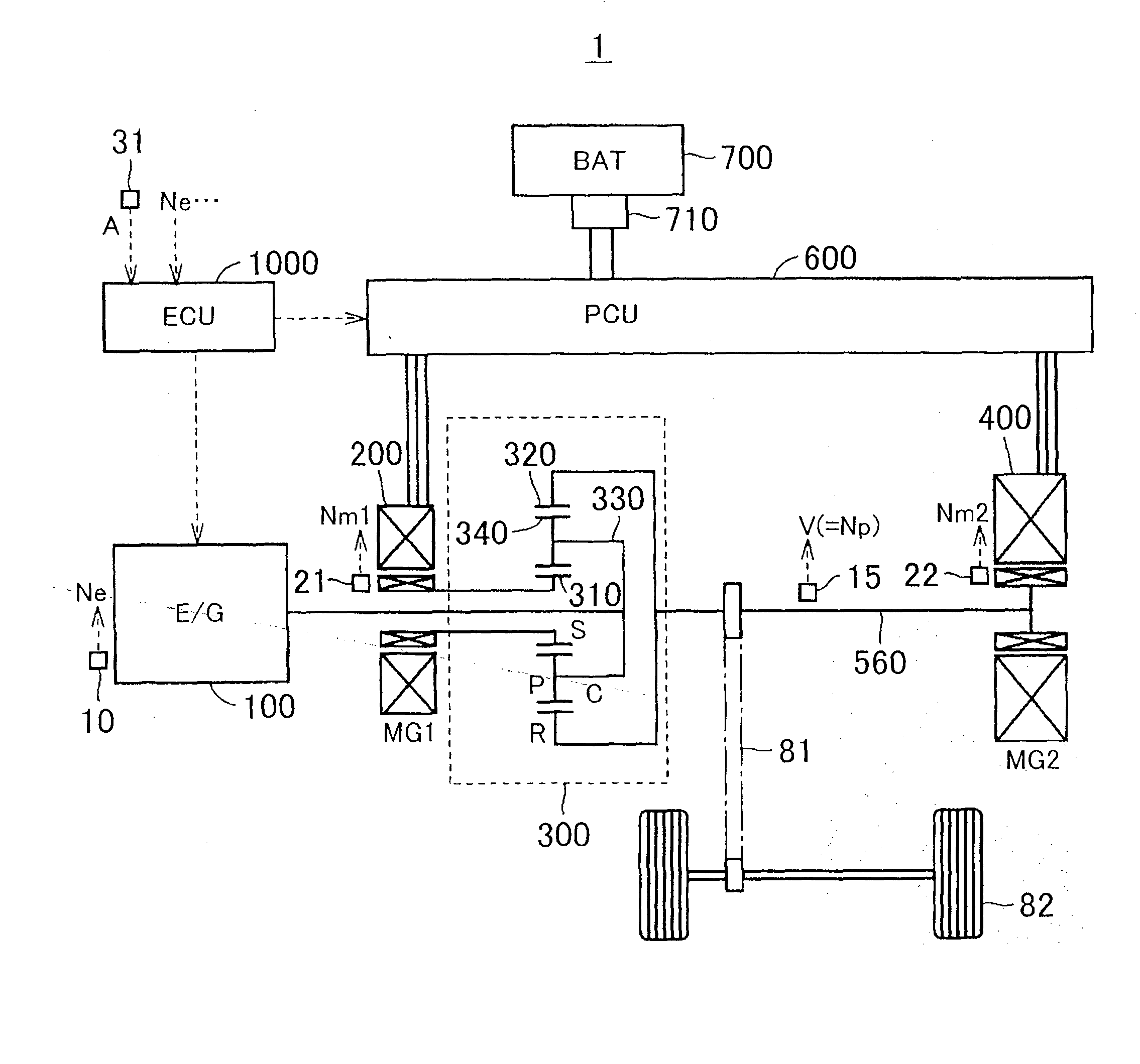
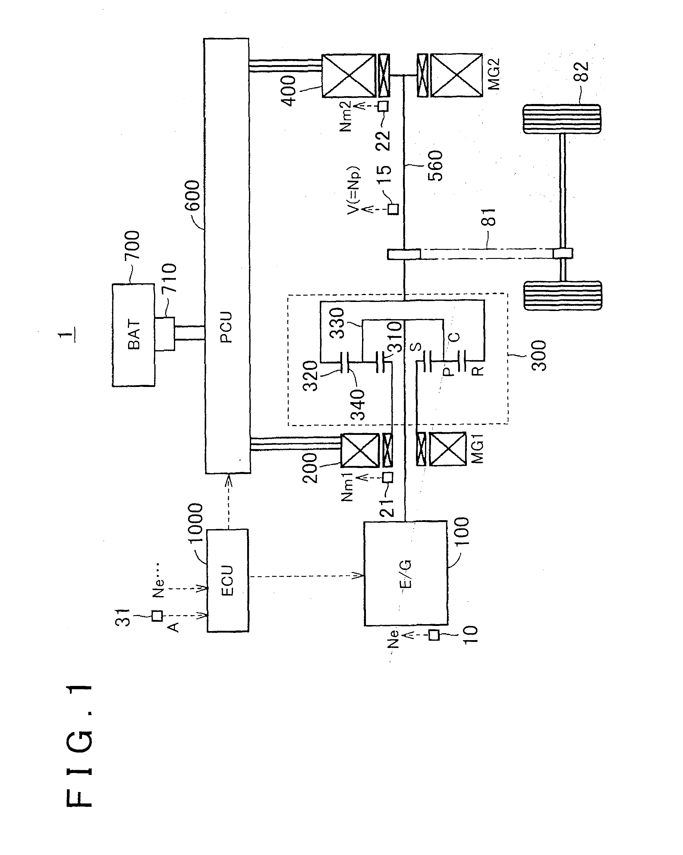
[0033]FIG. 1 is an overall block diagram of a vehicle 1 according to this embodiment. The vehicle 1 includes an engine 100, a first MG 200, a power distribution mechanism 300, a second MG 400, a propeller shaft (output shaft) 560, a power control unit (PCU) 600, a battery 700, a system main relay (SMR) 710, and an ECU 1000.

[0034]The engine 100 is an internal combustion engine that outputs power by burning a fuel. The power of the engine 100 is input into the power distribution mechanism 300.

[0035]The power distribution mechanism 300 divides the power input from the engine 100 into power for the output shaft 560 and power for the first MG 200.

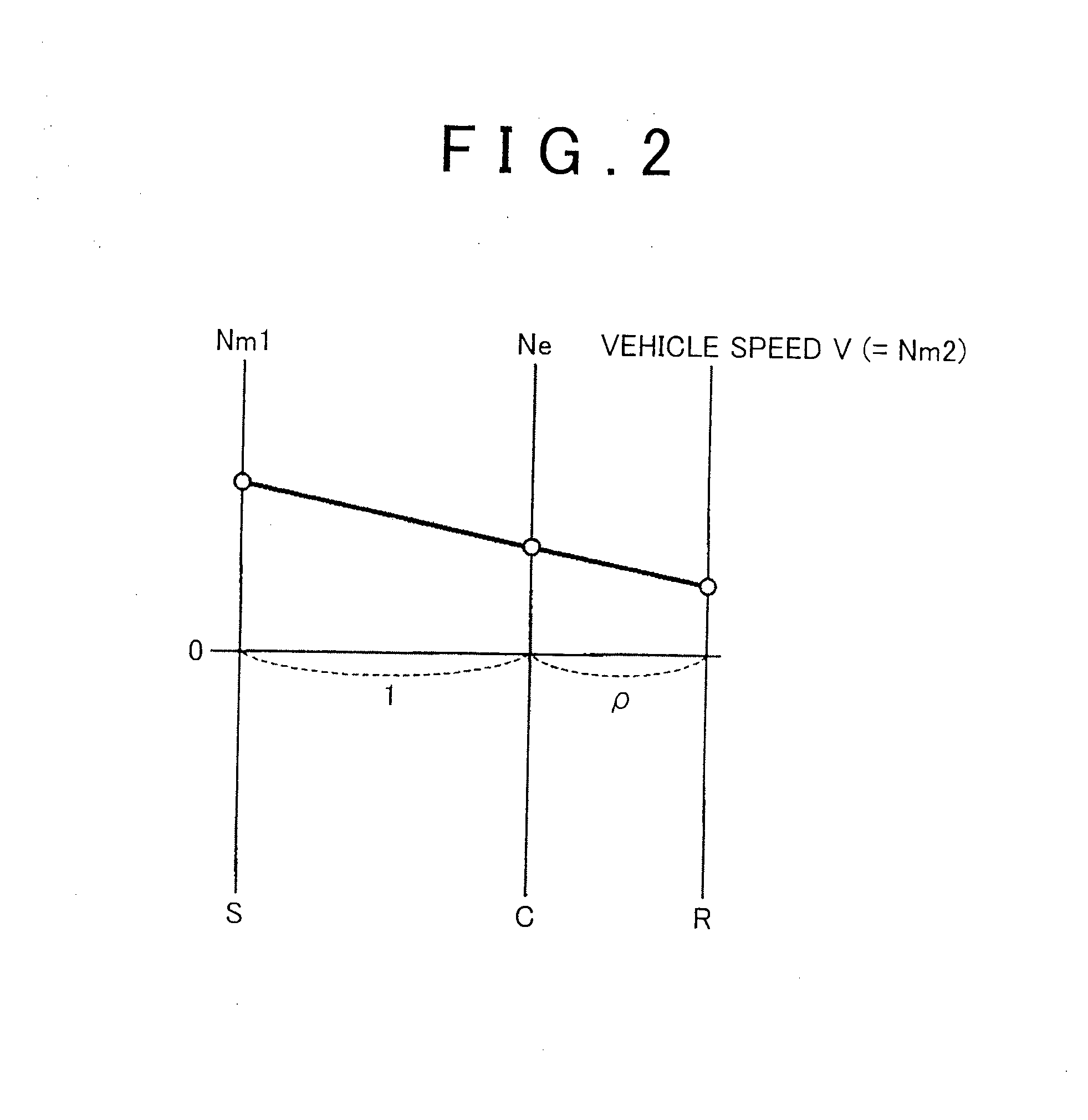
[0036]The power distribution mechanism 300 is a planetary gear mechanism having a sun gear (S) 310, a ring gear (R) 320, a pinion gear (P) 340 meshed to the sun gear (S) 310 and the ring gear (R) 320, and a carrier (C) 330 that holds the pinion gear (P) 340 to be free to rotate and revolve.

[0037]The carrier (C) 330 is coupled to a crankshaft of ...

second embodiment

[0090]FIG. 10 is an overall block diagram of a vehicle 1a according to this embodiment. The vehicle 1a differs from the vehicle 1 shown in FIG. 1 in that a transmission 500 is provided between the second MG 400 and the output shaft 560. All other structures are identical to the vehicle 1 shown in FIG. 1, and therefore detailed description thereof will not be repeated.

[0091]The transmission 500 shifts the rotation speed of the second MG 400 and transmits the shifted rotation to the output shaft 560. The transmission 500 is constituted by a set of Ravigneaux planetary gear mechanisms. More specifically, the transmission 500 includes a first sun gear (S1) 510, a second sun gear (S2) 520, a first pinion (P1) 531 meshed to the first sun gear (S1) 510, a second pinion (P2) 532 meshed to the first pinion (P1) 531 and the second sun gear (S2) 520, a ring gear (R1) 540 meshed to the second pinion (P2) 532, and a carrier (C1) 550 that holds the respective pinions 531, 532 to be free to rotate...


PUM


Abstract

In a hybrid vehicle including an engine, a motor, a generator, and a battery that is electrically connected to the motor and the generator, an ECU performs “battery-less travel control” enabling the vehicle to travel when a fault occurs in the battery by disconnecting the battery from an electrical system including the motor and the generator and driving the motor using power that is generated by the generator using the power of the engine. When the battery-less travel control is underway and a vehicle speed V exceeds a vehicle speed limit Vsh, the ECU implements a vehicle speed limitation. As a result, a control mode of the motor is less likely to shift to a rectangular control mode during the battery-less travel control.

Description

BACKGROUND OF THE INVENTION[0001]1. Field of the Invention[0002]The invention relates to a vehicle, and more particularly to a vehicle that travels using electric power from at least one of an engine and a motor.[0003]2. Description of Related Art[0004]Recently, hybrid vehicles that travel using drive power from at least one of an engine and a motor are becoming more widespread. A hybrid vehicle may include a generator provided separately to the motor in order to generate electric power using the power of the engine.[0005]Japanese Patent Application Publication No. 2007-196733 (JP-2007-196733 A) discloses a technique employed in a hybrid vehicle including an engine, a motor, and a generator for performing control (also referred to hereafter as “battery-less travel control”). The hybrid vehicle disconnects the battery from an electrical system including the motor and the generator and drives the motor using power that is generated by the generator using the power of the engine to tra...

Claims


Application Information

Patent Timeline
IPC IPC(8): B60L15/20B60L50/16
CPCY10S903/903B60L15/20B60Y2306/13B60Y2300/68B60K6/34B60W10/08B60W10/105B60W2720/10B60W20/50Y02T10/72B60W20/00
Inventor TANAKA, NOBUYUKINAGATA, SHOJI
Owner TOYOTA JIDOSHA KK
Learn More