Automatic vehicle braking system and method

a technology of automatic vehicle braking and braking system, which is applied in the direction of braking system, analogue process for specific applications, instruments, etc., can solve the problems of unnecessarily operating of auto-adjusters, large shoe clearance, and inappropriate shoe clearan

Inactive Publication Date: 2011-08-04
TOYOTA JIDOSHA KK
View PDF22 Cites 13 Cited by
  • Summary
  • Abstract
  • Description
  • Claims
  • Application Information

AI Technical Summary

Benefits of technology

[0039]The automatic vehicle braking system according to the invention brings about the effect that braking during the automatic braking is stabilized.

Problems solved by technology

However, when the brake shoes exert a large pressing force on the brake drum and the brake drum is elastically deformed, or when the brake drum is heated to high temperatures and the brake drum is thermally expanded at the time of braking, the shoe clearance can become large, which can cause the auto-adjuster to be unnecessarily operated.
When the auto-adjuster is unnecessarily operated in this way, the shoe clearance can become an inappropriate size and in this case, the desired braking force is not obtained.
However, the change in the braking force of the drum brake in response to the change in the hydraulic pressure when the hydraulic pressure is applied to generate a braking force is not uniform and therefore, it is difficult to apply a desired braking force when the braking force is generated in the drum brakes by the automatic braking control.
Thus, when the automatic braking control is performed in a vehicle in which the front wheels are provided with disc brakes and the rear wheels are provided with drum brakes, it is difficult to control the braking force of the drum brakes and therefore, there has been a case where the deceleration of the vehicle becomes unstable.
Further, because the braking force of the drum brakes is unstable in the early stage of braking, when the disc brakes and the drum brakes are both used in a vehicle, there is a case where the braking force of the drum brakes, of which the braking force has not become stable yet, is also fed back when feedback control is performed during the automatic braking.
In this case, the actual braking force that has not become stable yet is fed back and therefore, the target braking force that is corrected according to the feedback also becomes unstable, which can result in a situation where the braking does not become stable and hunting occurs.
Thus, brake feeling during the automatic braking can be deteriorated.

Method used


Image

  • Automatic vehicle braking system and method
  • Automatic vehicle braking system and method
  • Automatic vehicle braking system and method

Examples


first embodiment

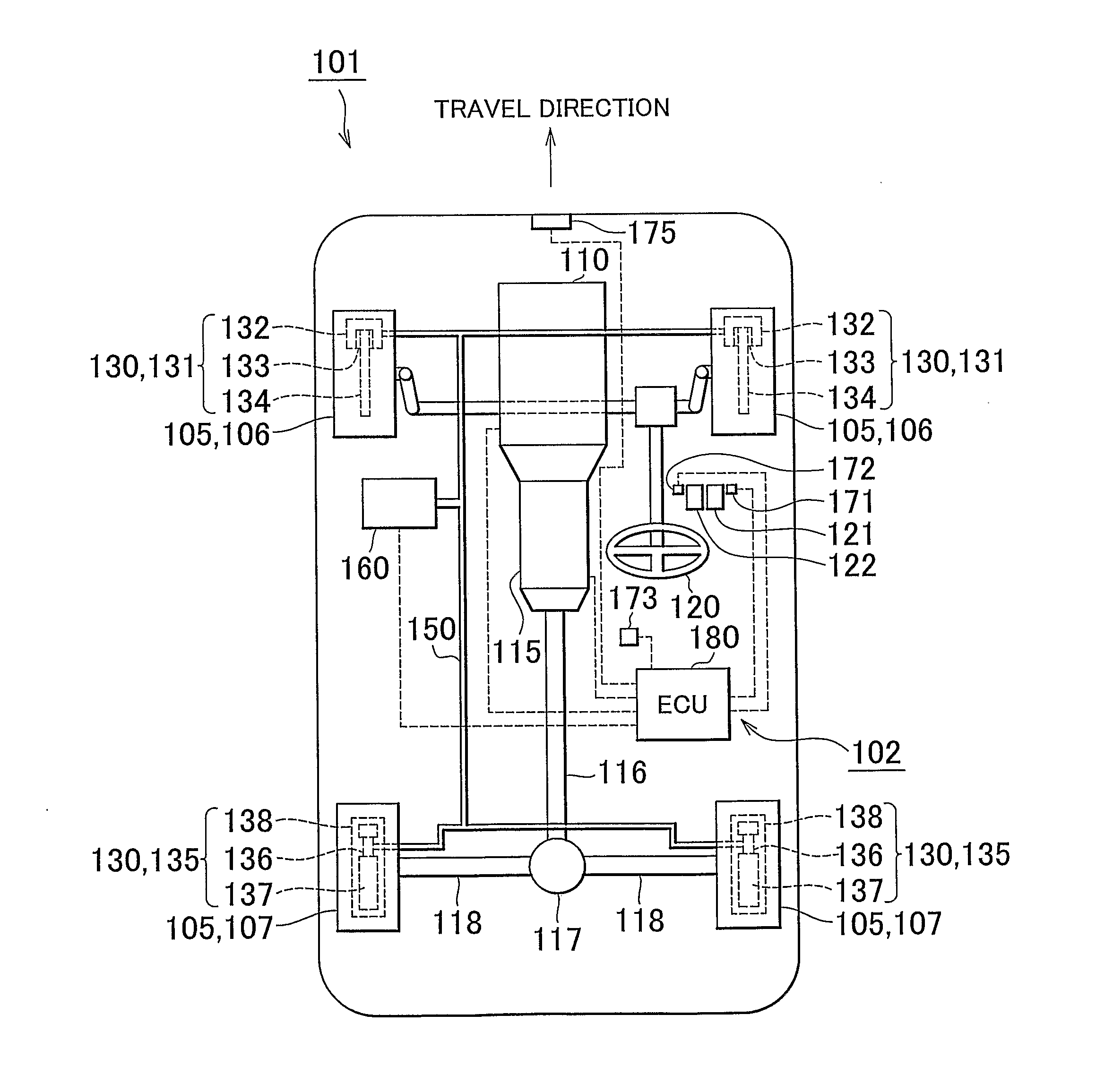
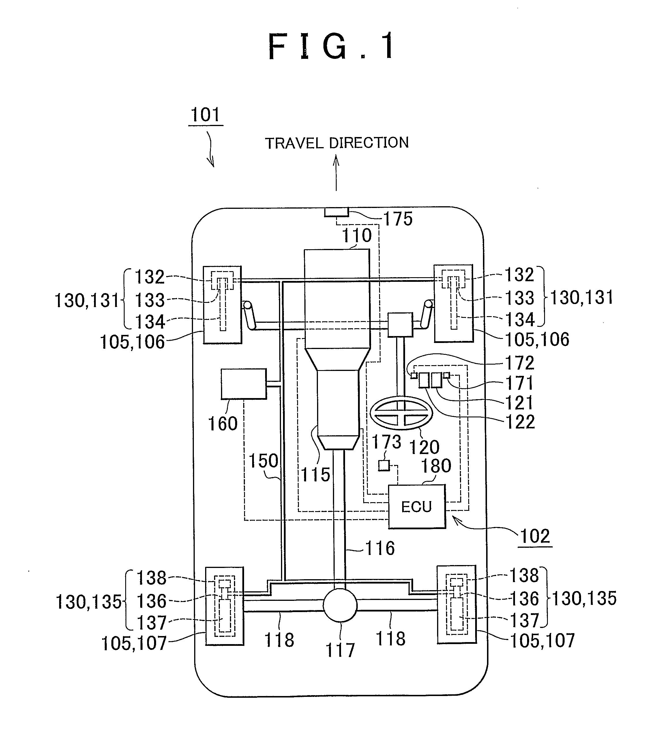
[0057]FIG. 1 is a schematic diagram of a vehicle provided with an automatic vehicle braking system according to the invention. In the following description, the travel direction of the vehicle 101 in the normal running condition is the forward direction and the direction opposite to the travel direction is the backward direction. In the vehicle 101 including the automatic vehicle braking system 102 according to this embodiment, an engine 110, which is an internal combustion engine, is mounted as the motive power generation means in a front area with respect to the travel direction of the vehicle 101. The motive power generated by the engine 110 is changed in speed by an automatic transmission 115 by a speed ratio appropriate to the running conditions. The motive power changed in speed by the automatic transmission 115 is transmitted to, among wheels 105 of the vehicle 101, rear wheels 107 provided as the driving wheels, via a propeller shaft 116, a differential gear 117, and a drive...

second embodiment

[0131]FIG. 8 is a schematic diagram of a vehicle provided with an automatic vehicle braking system according to the invention. Disc brakes231 and drum brakes 235 are connected to a hydraulic system 240 composed of lines for applying hydraulic pressure to the disc brakes 231 and the drum brakes 235 when the vehicle 201 is braked. Specifically, wheel cylinders 232 of the disc brakes 231 and wheel cylinders 236 of the drum brakes 235 are connected to the hydraulic system 240. The hydraulic system 240 is provided with a brake actuator 245 that controls the hydraulic pressure in the hydraulic system 240 when the vehicle 201 is braked. The brake actuator 245 controls hydraulic pressure, which is used as the applied force that is applied to the disc brakes 231 and the drum brakes 235, by one control system. Specifically, when the vehicle 201 is braked, the hydraulic pressure used to actuate the brakes 230 is controlled in such a manner that the control of the disc brakes 231 and the contro...

third embodiment

[0171]The front-wheel brake actuator 2105 and the rear-wheel brake actuator 2106 are both connected to an ECU 2110. The braking force of the disc brakes 231 is controlled by controlling the hydraulic pressure generated in the front-wheel brake actuator 2105 and the braking force of the drum brakes 235 is controlled by controlling the hydraulic pressure generated by the rear-wheel brake actuator 2106. In this way, in the automatic vehicle braking system 2100 the disc brakes 231 and the drum brakes 235 are provided so that the hydraulic pressures are controlled independently of each other.

[0172]FIG. 13 is a main part configuration diagram of the automatic vehicle braking system shown in FIG. 12. The ECU 2110 that the automatic vehicle braking system 2100 according to the third embodiment has includes the processing section 271, the storage section 285, and the input / output section 286, similarly to the ECU 270 that the automatic vehicle braking system 202 according to the second embo...


PUM


Abstract

Provided in a vehicle, in which front wheels are provided so as to be braked by disc brakes and rear wheels are provided so as to be braked by drum brakes, is an automatic braking control section that controls the deceleration of the vehicle by adjusting only the hydraulic pressure applied to the disc brakes when the automatic braking control is performed. Thus, when the automatic braking control is performed, the braking force of the drum brakes is not adjusted and therefore, it is possible to suppress the instability of the deceleration of the vehicle caused by adjusting the braking force of the drum brakes of which the braking force is difficult to control. As a result, it is possible to stabilize braking when the automatic braking is performed.

Description

BACKGROUND OF THE INVENTION[0001]1. Field of the Invention[0002]The invention relates to an automatic vehicle braking system and method, and in particular relates to an automatic vehicle braking system and method that perform the automatic braking of a vehicle in which both a disc brake and a drum brake are used.[0003]2. Description of the Related Art[0004]A conventional vehicle includes an automatic vehicle braking system that automatically performs braking as needed, independently of the braking operation by the driver, in order to secure safety during traveling and driving stability. Such an automatic vehicle braking system is used, for example, when traction control is performed that is control performed to suppress wheel spin by reducing the rotation speed of the wheel at which the wheel spin occurs by automatic braking control when the wheel slip due to driving force, which is the wheel spin, occurs because an excessive driving force is applied to the wheel.[0005]Popular brake...

Claims


Application Information

Patent Timeline
Patent Type & Authority Applications(United States)
IPC IPC(8): B60T7/12B60T8/17
CPCB60T7/22B60T13/686B60T8/1766B60T8/175
Inventor KATO, HIDEHISAKAJITA, HISASHI
Owner TOYOTA JIDOSHA KK
Why Eureka
Try Eureka