Multi-blade centrifugal fan and air conditioner employing the same

a centrifugal fan and multi-blade technology, applied in the direction of liquid fuel engines, semiconductor/solid-state device details, lighting and heating apparatus, etc., can solve the problems of generating abnormal noise (irritating noise), suppress deviation thereof, prevent flow reversal and flow separation near the tongue portion, suppress secondary flow in a direction perpendicular to the main flow

Inactive Publication Date: 2015-04-21
MITSUBISHI HEAVY IND LTD
View PDF26 Cites 13 Cited by
  • Summary
  • Abstract
  • Description
  • Claims
  • Application Information

AI Technical Summary

Benefits of technology

[0037]With the multi-blade centrifugal fan of the present invention, flow reversal and flow separation near a tongue portion can prevented and turbulence in a main flow and fluctuations of vortices occurring near the tongue portion can be stabilized; therefore, the airflow in a region downstream of the tongue portion can be stabilized, deviation thereof can be suppressed, and low-frequency noise (abnormal noise), having frequency components near 500 Hz in particular, generated when turbulence in a flow near the tongue portion reaches the diffuser portion (an abruptly expanded portion of the channel) can be reduced.
[0038]In addition, with the multi-blade centrifugal fan of the present invention, with a sub-blade, the occurrence of flow reversal and turbulence in a main flow and vortices before and after the tongue portion can be suppressed and instability of a secondary flow in a direction perpendicular to the main flow can also be suppressed; therefore, low-frequency noise (abnormal noise) having frequency components near 250 Hz and near 500 Hz generated when turbulence in the flow before and after the tongue portion reaches the diffuser portion (an abruptly expanded portion of the channel) can be reduced.
[0039]Furthermore, with the multi-blade centrifugal fan of the present invention, unstable fluctuations of the vortices, in which flow reversal of a flow and vortices due to flow separation simultaneously occur near the tongue portion and the vortices swirl up from a lower portion of an axially expanded portion toward an upper portion thereof, can be suppressed by the vortex control plate; therefore, low-frequency noise (abnormal noise) having frequency components near 500 Hz generated when turbulence in the flow before and after the tongue portion reaches the diffuser portion (an abruptly expanded portion of the channel) can be reduced.
[0040]Additionally, with the air conditioner of the present invention, because a high-performance multi-blade centrifugal fan in which the occurrence of low-frequency noise is reduced can be installed, it is possible to achieve further noise reduction and performance enhancement in the air conditioner.

Problems solved by technology

With such a multi-blade centrifugal fan, it is known that flow reversal toward the impeller occurs near the tongue portion of the scroll casing and that an abnormal noise (irritating noise) is generated by interference between the impeller and the flow in the reverse flow region, vibrations due to turbulence in the flow and vortices in the reverse flow region, as well as interference between the scroll casing and turbulence in the main flow or the vortices, and so on.

Method used


Image

  • Multi-blade centrifugal fan and air conditioner employing the same
  • Multi-blade centrifugal fan and air conditioner employing the same
  • Multi-blade centrifugal fan and air conditioner employing the same

Examples


first embodiment

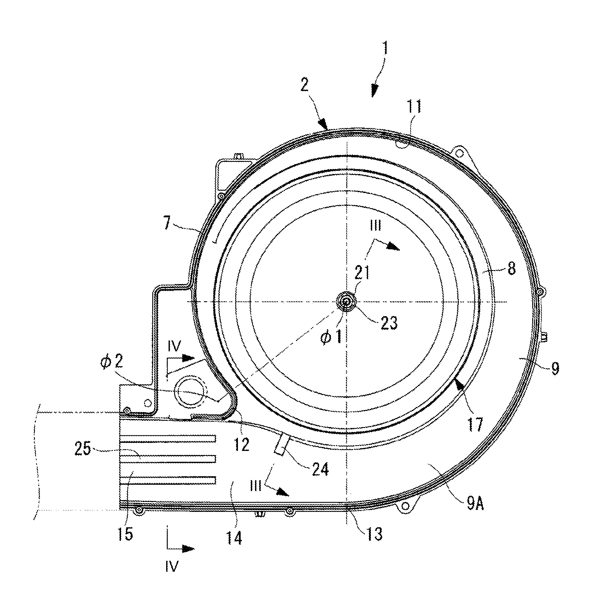
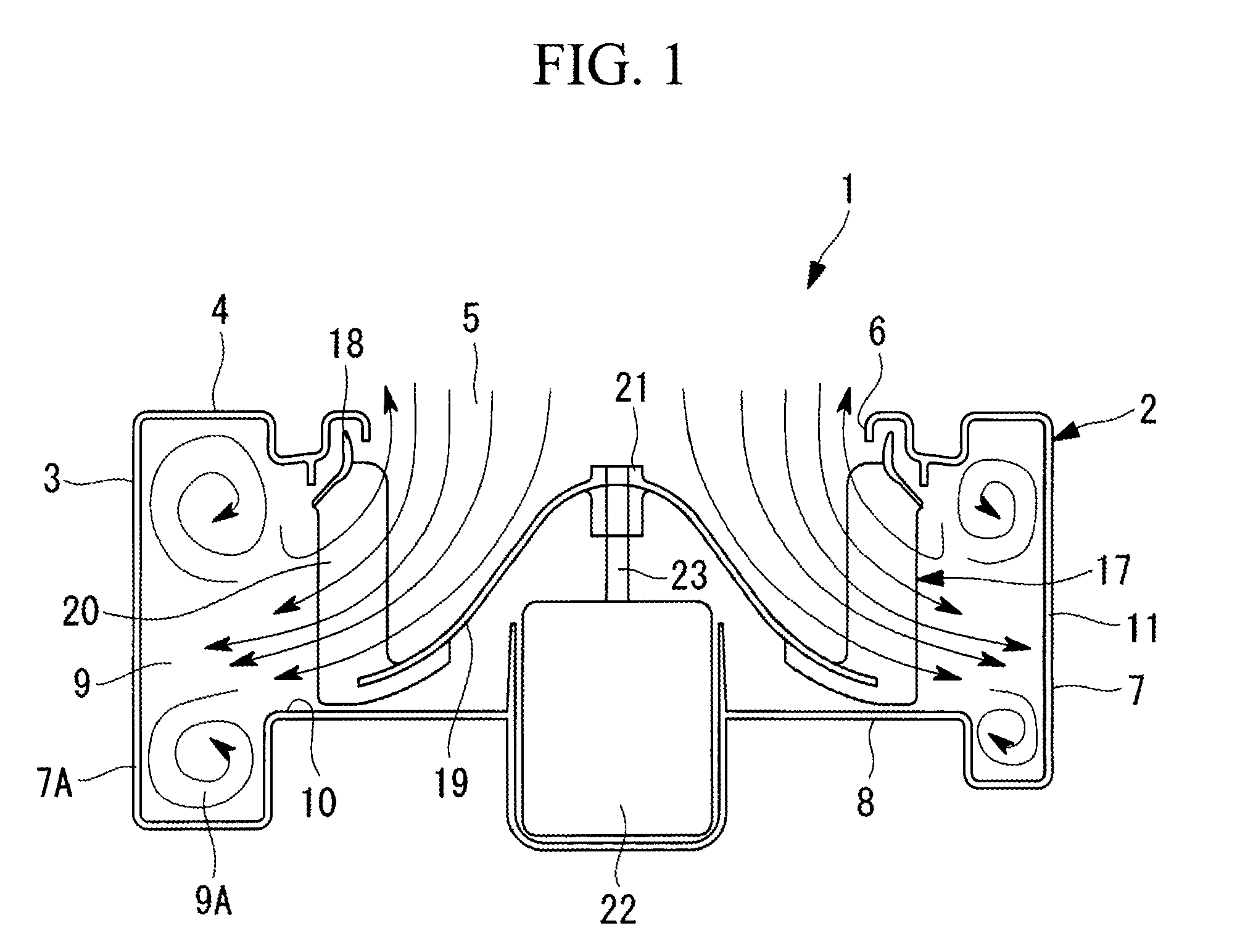
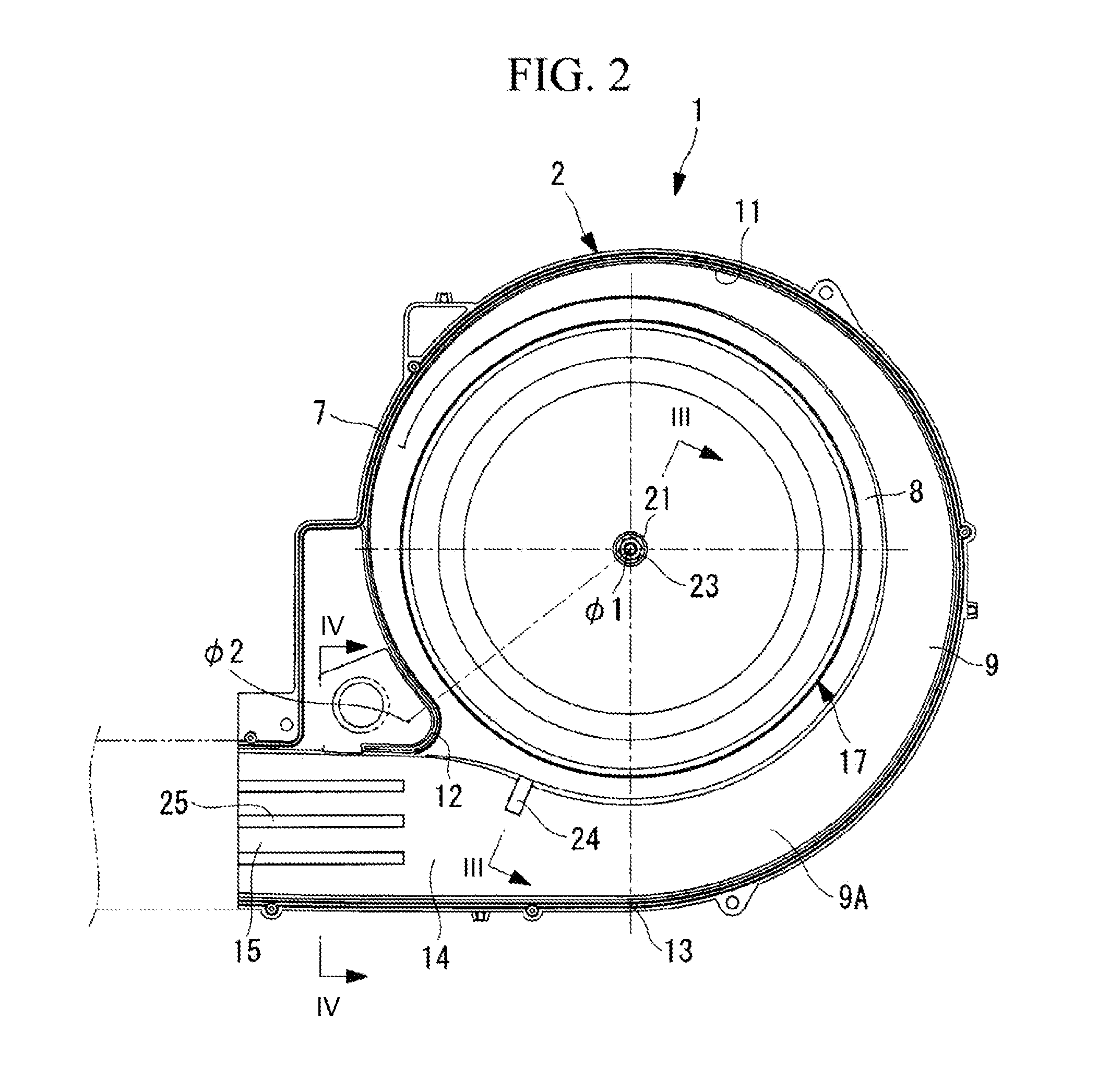
[0056]A first embodiment of the present invention will be described below by using FIGS. 1 to 4 and FIGS. 9 and 10. FIG. 1 shows a longitudinal sectional view of a multi-blade centrifugal fan according the first embodiment of the present invention, and FIG. 2 shows a lateral sectional view thereof, viewed from a lower-casing side.

[0057]A multi-blade centrifugal fan 1 is provided with a scroll casing 2 that is formed in a spiral shape (scroll shape) and is made of a plastic material.

[0058]The scroll casing 2 is formed of an upper casing 3 provided with a bell mouth 6, which forms an inlet 5 at a top surface 4, and a lower casing 7 in which an air channel 9 is formed at an outer circumference of an annular flange portion 8 that supports a motor 22 and an impeller 17. The upper casing 3 and the lower casing 7 are divided into two portions at an appropriate position in the vertical direction (rotation-axis direction), each of which is molded from a plastic material, and form the scroll ...

second embodiment

[0077]Next, a second embodiment of the present invention will be described by using FIGS. 5, 6, and 11.

[0078]The configuration of this embodiment differs from the above-described first embodiment in that a sub-blade 26 is provided instead of the protrusion 24 and the rib-like protrusions 25. Because other points are the same as those of the first embodiment, descriptions thereof will be omitted.

[0079]As shown in FIGS. 5 and 6, with the configuration of this embodiment, the sub-blade 26 that simultaneously controls a secondary flow and the occurrence of turbulence in an airflow and vortices is provided along an airflow direction at a position closer to the inner circumference than the center portion on the wall surface of the diffuser portion 15 in the region of the outlet 14, which is downstream of the spiral-end portion 13 of the scroll casing 2 provided in the axially expanded portion 7A of the lower casing.

[0080]When a center portion of the channel width at the wall surface of th...

third embodiment

[0085]Next, a third embodiment of the present invention will be described by using FIGS. 7, 8, 12, and 13.

[0086]The configuration of this embodiment differs from the above-described first embodiment in that a vortex control plate 27 and a secondary-flow control plate 29 are provided instead of the protrusion 24 and the rib-like protrusions 25. Because other points are the same as those of the first embodiment, descriptions thereof will be omitted.

[0087]As shown in FIGS. 7 and 8, in this embodiment, the vortex control plate 27, whose height in the rotation-axis direction is gradually increased over an area from upstream of the tongue portion 12 to an inner circumferential side surface in the region of the outlet 14, is provided near the tongue portion 12 in the region of the outlet 14, which is downstream of the spiral-end portion 13 of the scroll casing 2, in the axially expanded portion 7A provided in the lower casing 7. This vortex control plate 27 extends to a portion above the a...


PUM


Abstract

In a multi-blade centrifugal fan in which an impeller is provided in a scroll casing in a freely rotatable manner, the scroll casing is provided with an axially expanded portion that forms an air channel at a bottom surface thereof which is expanded in a rotation-axis direction at a radially outer side of an annular flange portion which supports the impeller; and is provided, in a region of an outlet between a tongue portion and a spiral-end portion of the scroll casing in the axially expanded portion, with a protrusion that protrudes radially outward from a radially inner side surface by a predetermined amount so as to directly face an airflow in a circumferential direction.

Description

TECHNICAL FIELD[0001]The present invention relates to a multi-blade centrifugal fan widely applied to air conditioners for vehicle air conditioning devices, etc., and to an air conditioner employing the same.BACKGROUND ART[0002]A multi-blade centrifugal fan in which an impeller having a plurality of blades is installed in a scroll casing that has its starting point at a tongue portion is widely applied to blower fans of refrigerating devices, air conditioning devices, or ventilation devices, etc. (hereinafter, simply referred to as air conditioners). In such a multi-blade centrifugal fan, air taken in, in an axial direction, from an inlet provided in a top surface of the scroll casing with the rotation of the impeller passes through between the plurality of blades of the impeller, is forcedly supplied from an inner circumferential side to an outer circumferential side, thereby changing its direction to a centrifugal direction (radial direction), is made to flow out to an air channel...

Claims


Application Information

Patent Timeline
Patent Type & Authority Patents(United States)
IPC IPC(8): F04D29/44F04D29/42F04D29/68
CPCF04D29/4226F04D29/441F04D29/681F05D2250/52F04D17/16F04D29/281
Inventor EGUCHI, TSUYOSHISUZUKI, ATSUSISATO, SEIJITAKAHASHI, MASAHIKO
Owner MITSUBISHI HEAVY IND LTD
Why Eureka
Try Eureka