Image Forming Apparatus and Image Forming Method

Inactive Publication Date: 2010-03-11
SEIKO EPSON CORP
View PDF5 Cites 1 Cited by
  • Summary
  • Abstract
  • Description
  • Claims
  • Application Information

AI Technical Summary

Benefits of technology

[0007]An advantage of some aspects of the invention is that it provides a technique of obtaining a sufficient developing density and simultaneously suppressing toner scattering to the inside and the outside of an apparatus and a base fog, for use with an image forming apparatus and an image forming method in a non-contact developing system in which a latent image holder and a toner carrying roller are opposed to each other with a gap therebetween.

Problems solved by technology

For example, image force or van der Waals force exerted on charged toner with a small size by the toner carrying roller is increased, and it becomes difficult for the charged toner to fly from the toner carrying roller.
Accordingly, it becomes difficult to develop an image with sufficient density.
This results in the image being dirty.
However, in this case, a larger amount of toner scatters, or a discharge occurs between the latent image holder and the toner carrying roller, resulting in an image being muddy.
On the other hand, when a toner fly electric field is increased to guarantee an amount of toner flying, toner scattering is likely to occur.
Particularly, toner that flies from the surface of the toner carrying roller opposed to the non-image portion to which the toner does not need to be adhered causes a problem.
Accordingly, it is difficult to reconcile a sufficient developing density and the suppression of the base fog and the toner scattering.
Since the binding force exerted on the non-contact toner toward the toner carrying roller is relatively small, the non-contact toner is likely to deviate from the surface of the toner carrying roller to scatter.
Since Coulomb force or van der Waals force is strongly exerted on the toner having a small particle size, the toner does not easily fly from the toner carrying roller.
Accordingly, it is more difficult to reconcile a sufficient developing density and the suppression of the base fog and the toner scattering, as compared with the case of using toner having a high particle size.

Method used


Image

  • Image Forming Apparatus and Image Forming Method
  • Image Forming Apparatus and Image Forming Method
  • Image Forming Apparatus and Image Forming Method

Examples


Embodiment Construction

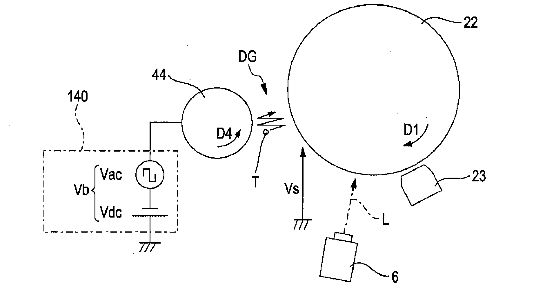
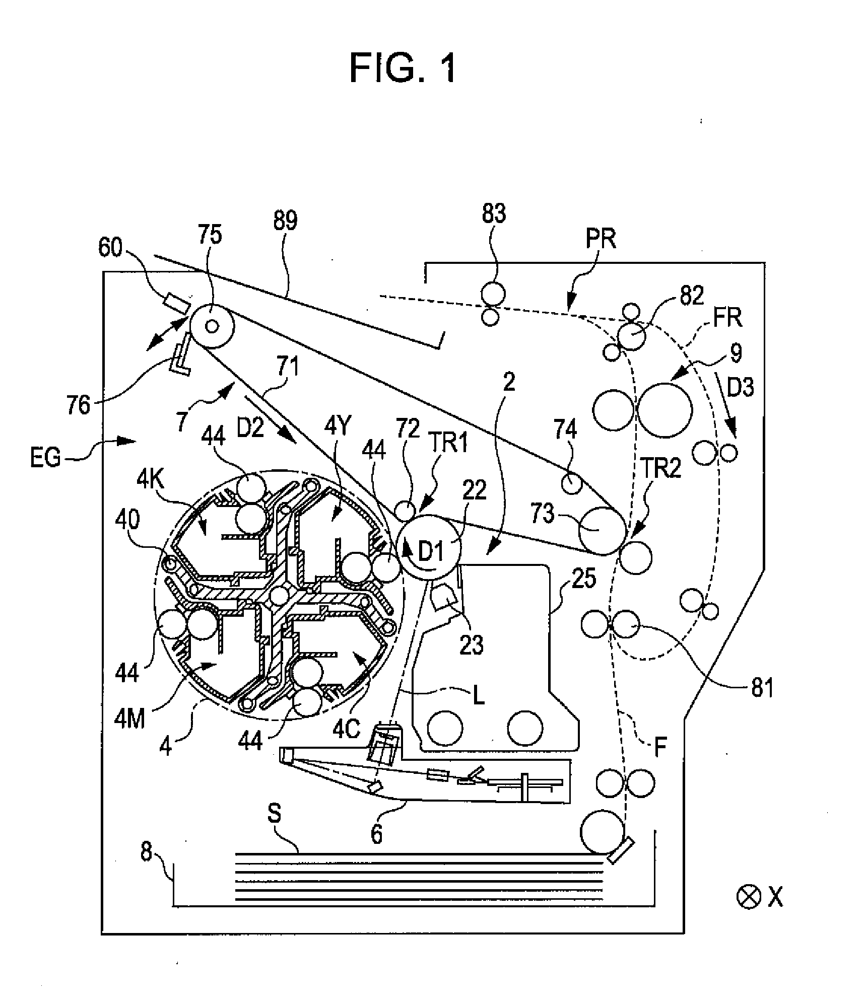
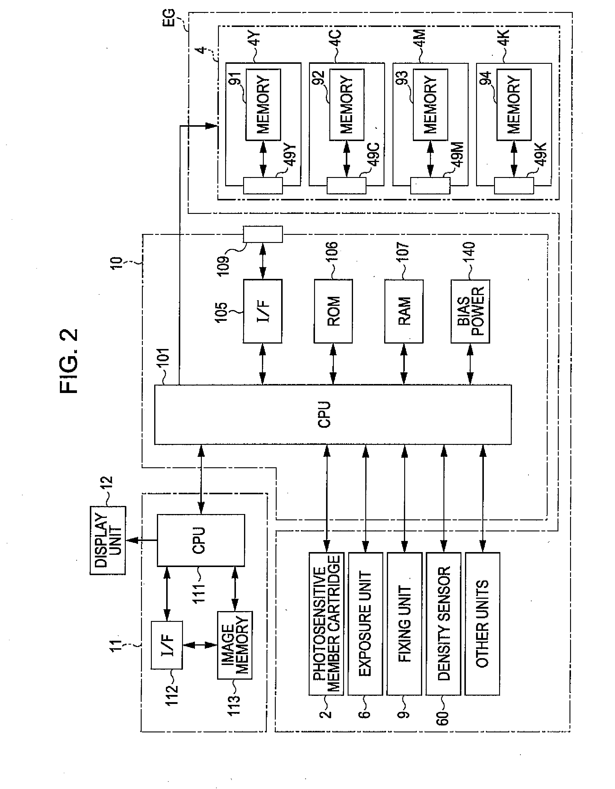
[0041]FIG. 1 is a diagram illustrating an image forming apparatus according to an embodiment of the invention. FIG. 2 is a block diagram illustrating an electrical configuration of the image forming apparatus of FIG. 1. This apparatus is an image forming apparatus for forming a full-color image by combining four color toners (developers); which are yellow (Y), cyan (C), magenta (M), and black (K), or forming a monochrome image using only a black (K) toner. In this image forming apparatus, when an image signal is input to a main controller 11 from an external apparatus such as a host computer, a CPU 101 of an engine controller 10 performs a predetermined image forming operation by controlling each unit in an engine unit EG according to a command from the main controller 11 and forms an image corresponding to the image signal on a sheet S.

[0042]In the engine unit EG, a photosensitive member 22 is provided to rotate in an arrow direction D1 of FIG. 1. In addition, around the photosensi...


PUM


Abstract

An image forming apparatus includes: a latent image holder that holds on its surface an electrostatic latent image in which an image portion and a non-image portion have different potentials; a toner carrying roller that carries a toner layer including both contact toner which directly contacts a surface of the roller and non-contact toner which contacts the contact toner but does not contact the surface of the roller; and an electric field forming unit that forms an alternating electric field to cause an electric field strength exerted between the non-image portion on the surface of the latent image holder and the surface of the toner carrying roller to be lower than a contact toner fly start electric field strength and higher than a non-contact toner fly start electric field strength, between the latent image holder and the toner carrying roller, as a toner fly electric field.

Description

BACKGROUND[0001]1. Technical Field[0002]The present invention relates to an image forming apparatus and an image forming method of developing an electrostatic latent image with toner while a latent image holder for holding an electrostatic latent image and a toner carrying roller for carrying toner are opposed to each other without being in contact.[0003]2. Related Art[0004]As a technique for developing an electrostatic latent image with toner, a technique of disposing a latent image holder for holding an electrostatic latent image and a toner carrying roller for carrying toner to be opposed to each other with a gap therebetween, and then developing an electrostatic latent image by causing the toner to fly into the gap, that is, a so-called non-contact developing method is known (for example, refer to JP-A-2007-127800). For this type of image forming apparatus, toner with a volume average particle size of 8 to 10 μm has been widely used. However, for the purpose of implementing high...

Claims


Application Information

Patent Timeline
IPC IPC(8): G03G15/08
CPCG03G2215/0619G03G15/0813
Inventor YAMADA, YOICHIMATSUMOTO, DAISUKEFUKUMOTO, TAKATOMO
Owner SEIKO EPSON CORP
Why Eureka
Try Eureka