Separator for fuel cell, method for producing separator, and solid oxide fuel cell

a technology of separator and fuel cell, which is applied in the direction of cell components, cell component details, electrochemical generators, etc., can solve the problems of power generation cell efficiency (output power density per unit area) being remarkably reduced, gradients to be formed, and damage to power generation cells, etc., to achieve the suppression of carburization deterioration of separator, the effect of improving the production efficiency of the separator and improving the carburizing resistan

Inactive Publication Date: 2010-04-29
YAMADA TAKASHI +7
View PDF6 Cites 1 Cited by
  • Summary
  • Abstract
  • Description
  • Claims
  • Application Information

AI Technical Summary

Benefits of technology

[0012]The present invention has been made in view of the above described circumstances. The principal object of the present invention is to provide a separator for fuel cell and a solid oxide fuel cell which are excellent in durability and can be used stably over a long period. More specifically, a first object of the present invention is to provide a separator for fuel cell and a solid oxide fuel cell which are capable of providing uniform gas concentration to the cell face and thereby improving the power generation efficiency, and which are capable of causing uniform temperature within the cell face and thereby preventing the power generation cell from being damaged. A second object of the present invention is to provide a separator for fuel cell which is excellent in carburizing resistance and which is capable of suppressing deterioration caused by carburization even when a hydrocarbon compound such as methane is used as fuel gas, and to provide a method for producing the separator, and a solid oxide fuel cell using the separator.
[0018]According to the first aspect of the present invention, multiple gas discharge ports are provided on approximately whole area of the layer surface of the separator, and the reactive gas (fuel gas, oxidizer gas) is made to be discharged like a shower from the gas discharge ports toward the power generation cell, as a result of which the gas concentration on the cell face can be made uniform. Therefore, deviation in the electrode reaction can be suppressed and current density within the cell can be made uniform, with the result that the output power density per unit area is increased so as to enable the power generation efficiency of the power generation cell as a whole to be remarkably improved, and that temperature distribution within the cell face is made uniform so as to prevent mechanical failure by thermal stress in the power generation cell.
[0019]Further, the wall surface of the hollow part and the inner flow passage of the separator, which surface is exposed to the reactive gas, are subjected to the aluminum diffusion coating treatment, so that it is possible to remarkably improve high temperature corrosion resistance of the wall surface, and to prevent deterioration of the separator caused by oxidization and carburization.
[0023]According to the second aspect of the present invention, all the surfaces exposed to the fuel gas, which include not only the surface of the separator but also the wall surface of the inner flow passage and the like, are plated with silver, copper, or one of silver and copper alloys, as a result of which carburizing resistance of the separator can be remarkably improved, and deterioration of the separator caused by carburization can be suppressed even when methane gas and the like is used as the fuel gas.
[0024]Further, one or both surfaces of the plate-shaped member are arranged to be plated with silver, copper, or one of silver and copper alloys, so that the plate-shaped members can be easily joined to each other by softening or melting the plating material on the layer surface of the plate-shaped members by heating the separator, as a result of which the production efficiency of the separator can be improved.
[0025]Further, the wall surface of the inner flow passage is arranged to be subjected to the aluminum diffusion coating treatment instead of the plating treatment of silver, copper, or one of silver and copper alloys, so that high temperature corrosion resistance of the separator can be further improved.

Problems solved by technology

This results in a problem that electrode reaction may not be uniform on the cell face to cause deviation of current density distribution within the cell face and thereby the efficiency of the power generation cell (output power density per unit area) may be remarkably decreased.
Further, the electrode reaction as exothermic reaction which is not uniformly performed within the cell face, causes a temperature gradient to be formed in the power generation cell, as a result of which the power generation cell may be damaged by thermal stress in the course of the reaction.
However, the fuel cell in which the separator made of stainless steel is adopted, has a problem that when a hydrocarbon compound, such as methane, is used as fuel gas, carbon and carbon oxide are generated by reforming reaction, so that a part exposed to the fuel gas, such as the fuel passage wall surface of the separator, is carburized by the reaction product and thereby the separator deteriorates in the early stage.

Method used


Image

  • Separator for fuel cell, method for producing separator, and solid oxide fuel cell
  • Separator for fuel cell, method for producing separator, and solid oxide fuel cell
  • Separator for fuel cell, method for producing separator, and solid oxide fuel cell

Examples


first embodiment

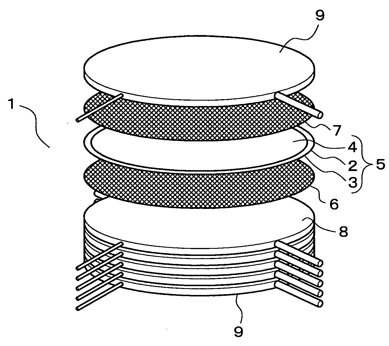
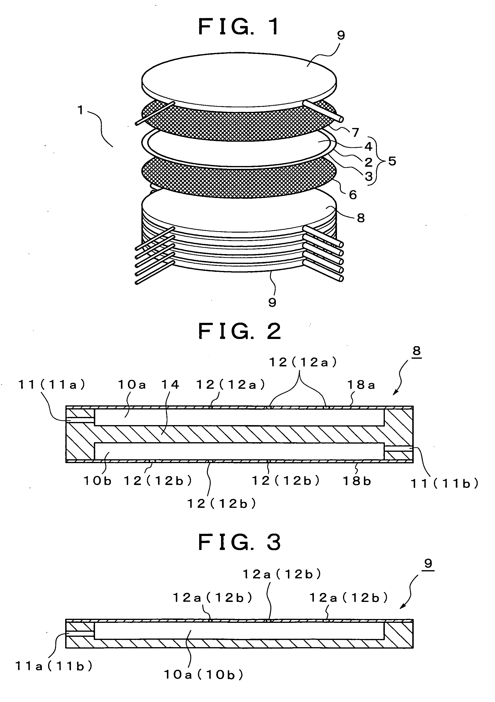
[0039]FIG. 1 shows a first embodiment of a solid oxide fuel cell according to the present invention, and reference numeral 1 in FIG. 1 denotes a fuel cell stack. As shown in FIG. 1, the fuel cell stack 1 has a constitution formed by laminating in order a power generation cell 5 in which a fuel electrode layer 3 and an air electrode layer 4 are arranged on both surfaces of a solid electrolyte layer 2, a fuel electrode current collector 6 on the outer side of the fuel electrode layer 3, an air electrode current collector 7 on the outer side of the air electrode layer 4, separators 8, (the uppermost and lowermost layer of which are formed as end plates 9), on the outer side of each of the current collectors 6, 7. In the fuel cell stack 1, a seal-less structure in which a gas leakage prevention seal is not particularly provided in the outer peripheral part of the power generation cell 5 is adopted.

[0040]Here, the solid electrolyte layer 2 is formed of stabilized zirconia (YSZ) doped wit...

second embodiment

[0053]FIG. 11 shows a second embodiment of the solid oxide fuel cell according to the present invention, in which the same components as those in the above described first embodiment are denoted by the same reference numerals and the explanation thereof is simplified.

[0054]The fuel cell stack 1 according to the present embodiment has a seal-less structure similar to the above described first embodiment, and has a constitution formed by laminating in order a power generation cell 5 in which a fuel electrode layer 3 and an air electrode layer 4 are arranged on both faces of a solid electrolyte layer 2, a fuel electrode current collector 6 on the outer side of the fuel electrode layer 3, an air electrode current collector 7 on the outer side of the air electrode layer 4, and separators 8 (the uppermost and lowermost layers of which are formed as end plates 9) on the outer side of each of the current collectors 6, 7.

[0055]The separator 8 has a function to electrically connect the power ...


PUM

PropertyMeasurementUnit
temperatureaaaaaaaaaa
areaaaaaaaaaaa
areaaaaaaaaaaa

Abstract

Gas discharge ports are provided in almost the entire area of a layer surface of a separator, and a gas for reaction is discharged like a shower from the separator toward a power generation cell. The separator is constructed by layering plate-shaped members containing iron-base alloy, nickel-base alloy, or chrome-base alloy as the base material. Silver, silver alloy, copper, or copper alloy is plated on both sides or one side of the base material of the plate-shaped member. The construction above can increase durability of a separator and enables the separator and a solid oxide fuel cell to be stably used for a long period.

Description

BACKGROUND OF THE INVENTION[0001]I. Technical Field[0002]The present invention relates to a separator for a fuel cell, a method for producing the separator, and a solid oxide fuel cell (SOFC).[0003]II. Description of the Related Art[0004]As is well known, the solid oxide fuel cell has been investigated and developed as one of various kinds of fuel cells for power generation. As the structure of the solid oxide fuel cell, there are proposed at present three types of structures: a cylindrical type, a monolithic type, and a flat plate laminated type. However, the flat plate laminated type structure is widely adopted for low-temperature operating type solid oxide fuel cell.[0005]In the flat plate laminated type solid oxide fuel cell, a fuel cell stack is constituted by alternately laminating power generation cells and separators in a state where a current collector is sandwiched between the power generation cell and the separator. The power generation cell has a laminated structure in w...

Claims


Application Information

Patent Timeline
Patent Type & Authority Applications(United States)
IPC IPC(8): H01M8/10H01M2/14H01M8/02H01M8/12
CPCH01M8/0206H01M8/021H01M8/0228Y02E60/525H01M8/0258H01M2008/1293Y02E60/50H01M8/025H01M8/0263H01M8/241H01M8/2457H01M8/2483
Inventor YAMADA, TAKASHIYAMADA, MASAHARUAKBAY, TANERHOSHINO, KOJIMIYAZAWA, TAKASHIKOTANI, TAKAFUMIKOMADA, NORIKAZUMURAKAMI, NAOYA
Owner YAMADA TAKASHI
Why Eureka
Try Eureka