Combustor

a combustor and gas turbine technology, applied in the direction of combustion process, hot gas positive displacement engine plant, lighting and heating apparatus, etc., can solve the problems of unstable flow of compressed air inside the combustor, and the above-mentioned flow becomes unstable, so as to minimize the disturbance of the flow

Active Publication Date: 2007-08-30
MITSUBISHI POWER LTD
View PDF6 Cites 16 Cited by
  • Summary
  • Abstract
  • Description
  • Claims
  • Application Information

AI Technical Summary

Benefits of technology

[0017] It is an object of the present invention to provide a combustor which can uniformize the flow of compressed air flowing toward tips of main nozzles and minimize disturbance thereof.
[0025] In accordance with the present invention, by providing notches at the tip of the cylinder, vortices are generated in the air flow by the tangential cus / protuberances and the vortices can be fixed. Then, the vortices being generated in the air flow can determine the direction of the air flow so as to flow toward the tips of the main nozzles. As a result, the air flow flowing toward the tips of the main nozzles can be stabilized. In addition, because a high pressure compressed air is supplied to the combustor, vortices being generated by the notches become small, which enables suppression of instability and pressure loss of the flow due to the vortices.

Problems solved by technology

However, the compressed air being supplied to the combustor 2 in a manner as described hereinabove becomes unstable in flowing inside the combustor2.
Due to these vortex flows, the flow of the compressed air inside the combustor basket 2 becomes unstable.
As a result, pressure distribution of the compressed air at the tips of the pilot nozzle 21 and the main nozzles 22 becomes imbalanced, resulting in unstable combustion thereof.
In consequence, not only the rate of occurrence of NOx becomes high but also durability becomes deteriorated due to generation of combustion oscillations.
However, because a difference occurs between the inside compressed air flow and the outside compressed air flow in turning, the uniformity thereof is not sufficient.
Moreover, there arises a problem of a significant pressure drop because resistance based on bending of the flow ring and guide vanes is significant.

Method used


Image

  • Combustor
  • Combustor
  • Combustor

Examples


first embodiment

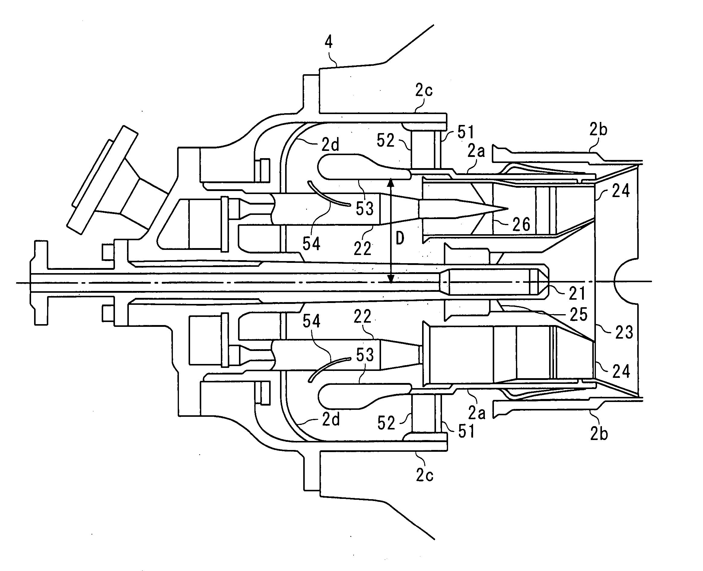
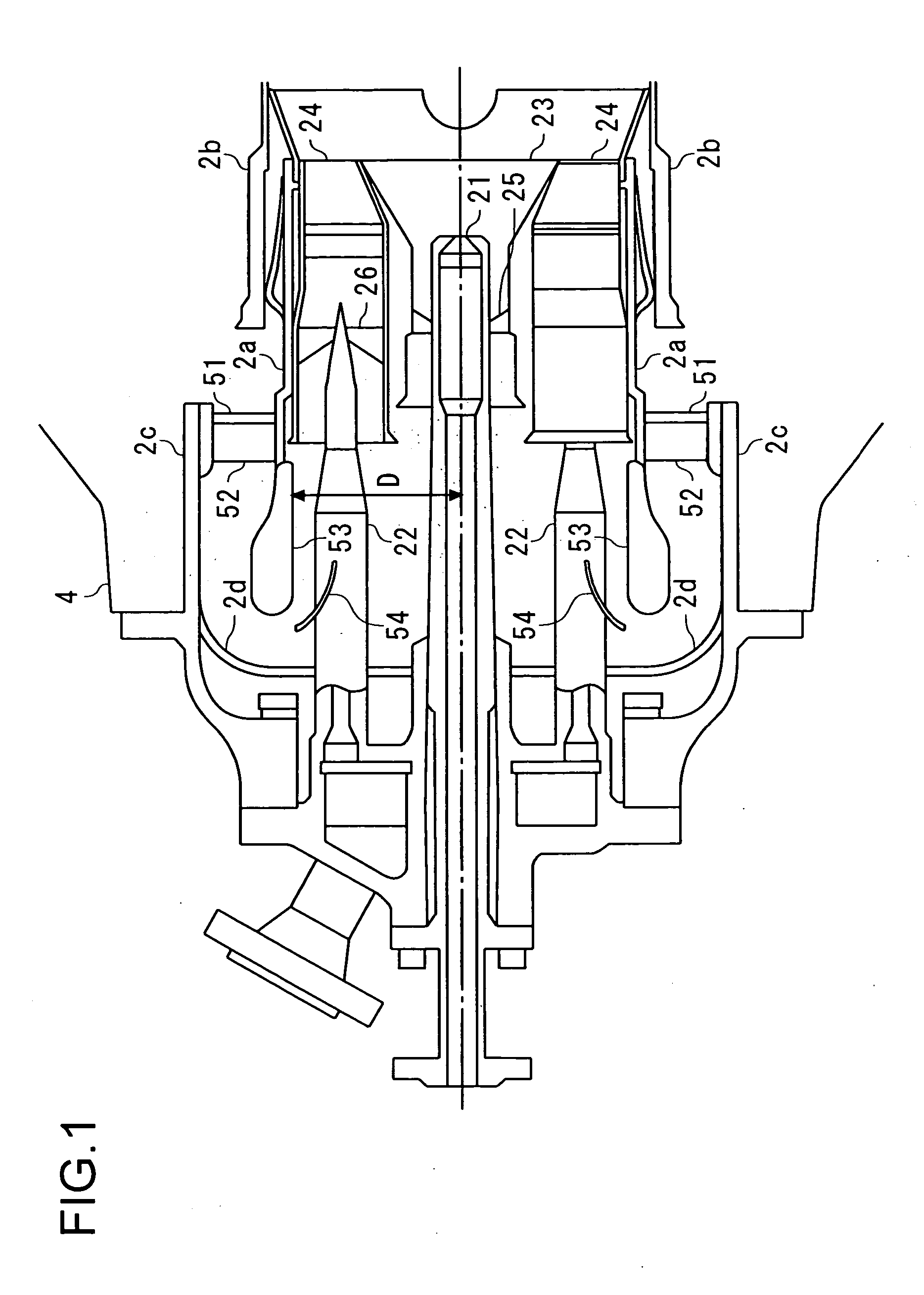
[0042] Referring now to the drawings, a first embodiment of the present invention will be described hereinafter. FIG. 1 is a schematic cross-sectional view showing a construction of an interior of a combustor basket in a combustor in accordance with the prevent embodiment. In the construction of a combustor of FIG. 1, same symbols will be supplied to portions that are used for same purpose as combustors shown in FIG. 13 and FIG. 14, and detailed explanation thereof will be omitted. In addition, the side of a transition piece inside a combustor basket will be referred as “downstream side,” while the side of a transition piece in a space between an external cylinder and a combustor basket will be referred as “upstream side.”

[0043] As shown in FIG. 1, same as a combustor of FIG. 13, a combustor in accordance with the present embodiment comprises a pilot nozzle 21 being provided to a center thereof and performing diffusion combustion; a plurality of main nozzles 22 being provided circum...

second embodiment

[0058] A second embodiment of the present invention will be described hereinafter by referring to the drawings. The combustor in accordance with the present embodiment has a cylinder being provided with the side of the bases of the pilot nozzle 21 and the main nozzles 22 constructed in a different manner from the first embodiment. However, the remaining parts of the construction of the combustor with the present embodiment has a same construction as the combustor in accordance with the first embodiment. Therefore, different parts of construction of the cylinder from the first embodiment will be explained hereinafter. FIG. 6 is a perspective view showing an approximate construction of a part of a cylinder of the combustor with the present embodiment. FIG. 7 is a front view of the upstream-side end of the cylinder viewed from the side of the bases of the pilot nozzle 21 and the main nozzles 22.

[0059] Same as the cylinder 53 provided to the combustor with the first embodiment (See FIG...


PUM


Abstract

By installing a cylinder 53x having a bell-mouth construction to the downstream side of a combustor basket 2a and by providing different level to the downstream-side end of the cylinder 53x, notches 60 are constructed. The notches 60 form fixed vortices in the compressed air, and the vortices enable the compressed air to determine the flow direction thereof so as to flow toward the tips of the main nozzles 22.

Description

BACKGROUND OF THE INVENTION [0001] 1. Field of the Invention [0002] The present invention relates to a gas turbine combustor, and especially, relates to a combustor which is so constructed as to reduce drift and disturbance of airflow flowing through the interior thereof. [0003] 2. Description of the Prior Art [0004] A cross-sectional view of FIG. 12 shows a general construction of a gas turbine. As shown in FIG. 12, a gas turbine comprises a compressor 1 compressing the air; combustors 2 being supplied with the air compressed by the compressor 1 and fuels so as to perform combustion; and a turbine 3 being rotary driven by combustion gas from the combustors 2. The compressor 1, the combustors 2 and the turbine 3 are covered by casings 4, respectively. In addition, a plurality of the combustors 2, sixteen pieces for example, are arranged on the outer circumference of a rotor 5 serving as one shaft sharing the compressor 1 and the turbine 3, being equally spaced. [0005] In a gas turbi...

Claims


Application Information

Patent Timeline
Patent Type & Authority Applications(United States)
IPC IPC(8): F23R3/20
CPCF23R3/286F23R3/04
Inventor TANIMURA, SATOSHIKURIHARA, KENTASAITOH, TOSHIHIKORODRIGUEZ, JOSE
Owner MITSUBISHI POWER LTD
Why Eureka
Try Eureka