Radar level gauge with antenna arrangement for improved radar level gauging

a technology of antenna arrangement and radar level, which is applied in the direction of engine lubrication, liquid/fluent solid measurement, reradiation, etc., can solve the problems of easy damage, small connectors, and severe deformation, so as to improve the ability to distinguish and improve the sensitivity

Inactive Publication Date: 2006-09-12
ROSEMOUNT TANK RADAR
View PDF5 Cites 33 Cited by
  • Summary
  • Abstract
  • Description
  • Claims
  • Application Information

AI Technical Summary

Benefits of technology

[0012]A further object of the present invention is to provide a radar level gauge having improved gauging sensitivity at small distances and minimizing any disturbances of a weak surface echo by any internal echoes.
[0021]A further advantage of the radar level gauge and method in accordance with the present invention is that the ability to replace a faulty electronic unit while an associated tank is pressurized is enabled.

Problems solved by technology

The extension of the use to more diversified applications has posed a number of challenges on the design of radar level gauges.
Field experience however is that the tiny connectors, which are necessary for high frequency use, may easily be damaged during handling outside of laboratory environments and that they will degrade severely if even a very small amount of water, a 0.1 mm layer or less, or dirt is trapped inside at handling during certain weather conditions.
Furthermore all radar systems need some duplexing function to use the same physical antenna for transmitting and receiving and typically that introduces two-way losses of 6–10 dB or more with the simple system used in most radar level gauges.
The complex mechanics involved also indicates a far too high cost for the typical process use.
Also, this arrangement is intended for use in connection with large storage tanks and not suited for measurements in smaller size tanks, such as process tanks, which usually are of substantially smaller physical dimensions.

Method used


Image

  • Radar level gauge with antenna arrangement for improved radar level gauging
  • Radar level gauge with antenna arrangement for improved radar level gauging
  • Radar level gauge with antenna arrangement for improved radar level gauging

Examples


Embodiment Construction

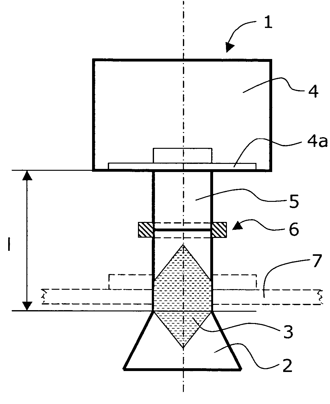
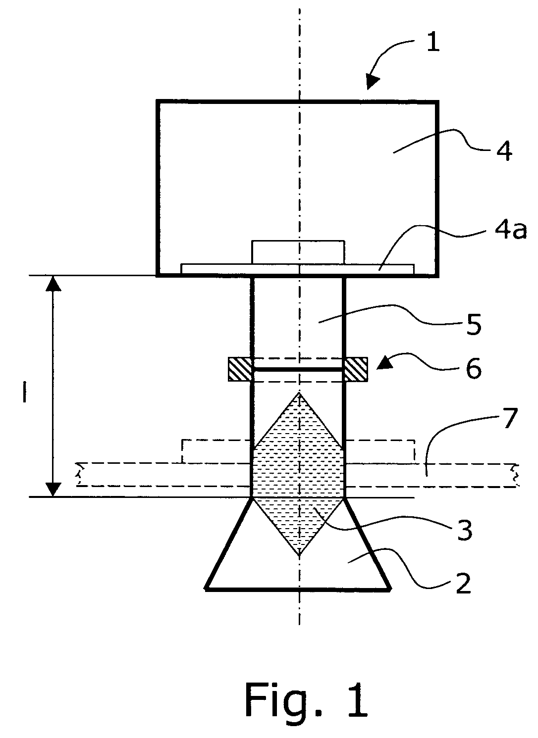
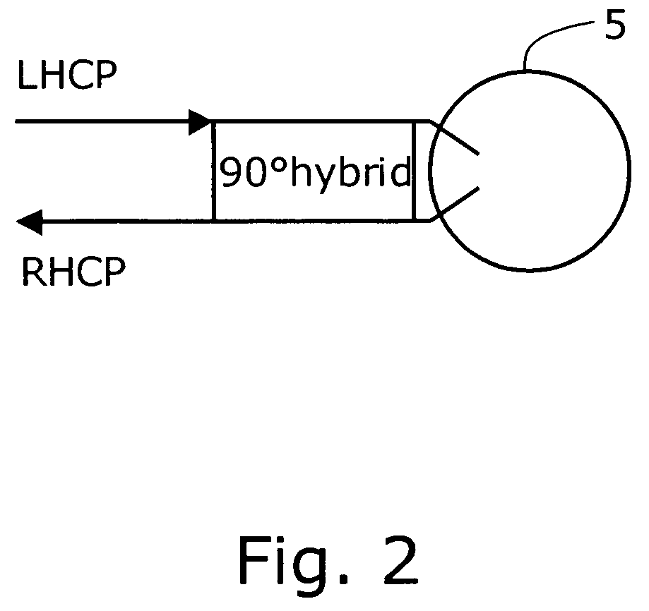
[0028]A radar level gauge 1 with an antenna arrangement for improved radar level gauging in accordance with the present invention and as illustrated in FIG. 1 comprises: an antenna 2, a tank sealing 3, an enclosed electronics unit 4 and a waveguide feed 5 between the electronics unit 4 and the antenna 2. The waveguide 5 is essentially straight and has a 90°-symmetric cross section and is arranged to accommodate two essentially orthogonal waveguide modes. Further, the waveguide 5 has a physical length below two times the range resolution or preferably below one range resolution. The physical length is counted from the microwave / electronic circuits (the circuit board) to the upper end of the antenna 2 and is thus representative for the length when a small antenna 2 is used, typical in cases when this internal distance is critical as will be discussed further down. For a definition of “range resolution” reference can for instance be made to pages 358–359 of “Radar Principles” by Peyton...


PUM


Abstract

The present invention relates to a radar level gauge (1) comprising an antenna (2), a tank sealing (3), an electronics unit (4) and a waveguide feed (5) between the electronics unit (4) and the antenna (2). The waveguide (5) is essentially straight and has a 90°-symmetric cross section and is further arranged to accommodate two essentially orthogonal waveguide modes. The waveguide (5) further has a length (I) below two times the range resolution of said radar level gauge (1). The present invention further relates to a method for improved radar level gauging using a radar level gauge (1) as above.

Description

FIELD OF THE INVENTION[0001]The present patent application relates to a radar level gauge with antenna arrangement for improved radar level gauging. The present patent application further relates to a method for improved radar level gauging using such a radar level gauge. The invention provides improved gauging sensitivity at small distances and any disturbances of a weak surface echo by any internal echoes will be minimized.BACKGROUND OF THE INVENTION[0002]Radar level gauging in all kinds of tanks has found a steadily increasing use since the mid-seventies. The extension of the use to more diversified applications has posed a number of challenges on the design of radar level gauges.[0003]Obvious basic functions for all radar level gauges are sealing of the tank, which may hold high pressure, dangerous contents etc., and sealing of the enclosure protecting the electronics of the radar level gauge, at least for outdoor environments applications and sometimes for open sea applications...

Claims


Application Information

Patent Timeline
Patent Type & Authority Patents(United States)
IPC IPC(8): G01F23/284G01S13/08G01S7/03
CPCG01S7/03G01F23/284
Inventor EDVARDSSON, KURT OLOV
Owner ROSEMOUNT TANK RADAR
Why Eureka
Try Eureka