Radial ball bearing retainer

a radial ball bearing and retainer technology, which is applied in the direction of rotary bearings, rolling contact bearings, shafts and bearings, etc., can solve the problems of the radial gap between the surface of the running channel and the ball bearing, and achieve the effect of reducing the rotational torque, and improving the lubrication characteristics of the radial ball bearing

Inactive Publication Date: 2005-05-10
MINEBEAMITSUMI INC
View PDF10 Cites 12 Cited by
  • Summary
  • Abstract
  • Description
  • Claims
  • Application Information

AI Technical Summary

Benefits of technology

[0009]The disclosed retainer overcomes the aforesaid shortcomings of the prior art when used in a radial ball bearing by improving the lubrication characteristics of the radial ball bearing, and thereby reducing the rotational torque. The lubrication characteristics of the radial ball bearing are improved due to prevention of the shearing of the lubricating oil.

Problems solved by technology

The larger diameter of the running channels results in a radial gap between the surface of the running channels and the balls.

Method used


Image

  • Radial ball bearing retainer
  • Radial ball bearing retainer
  • Radial ball bearing retainer

Examples


first embodiment

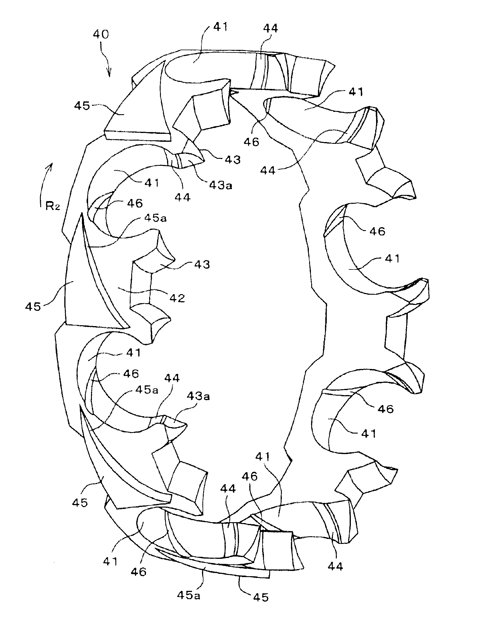
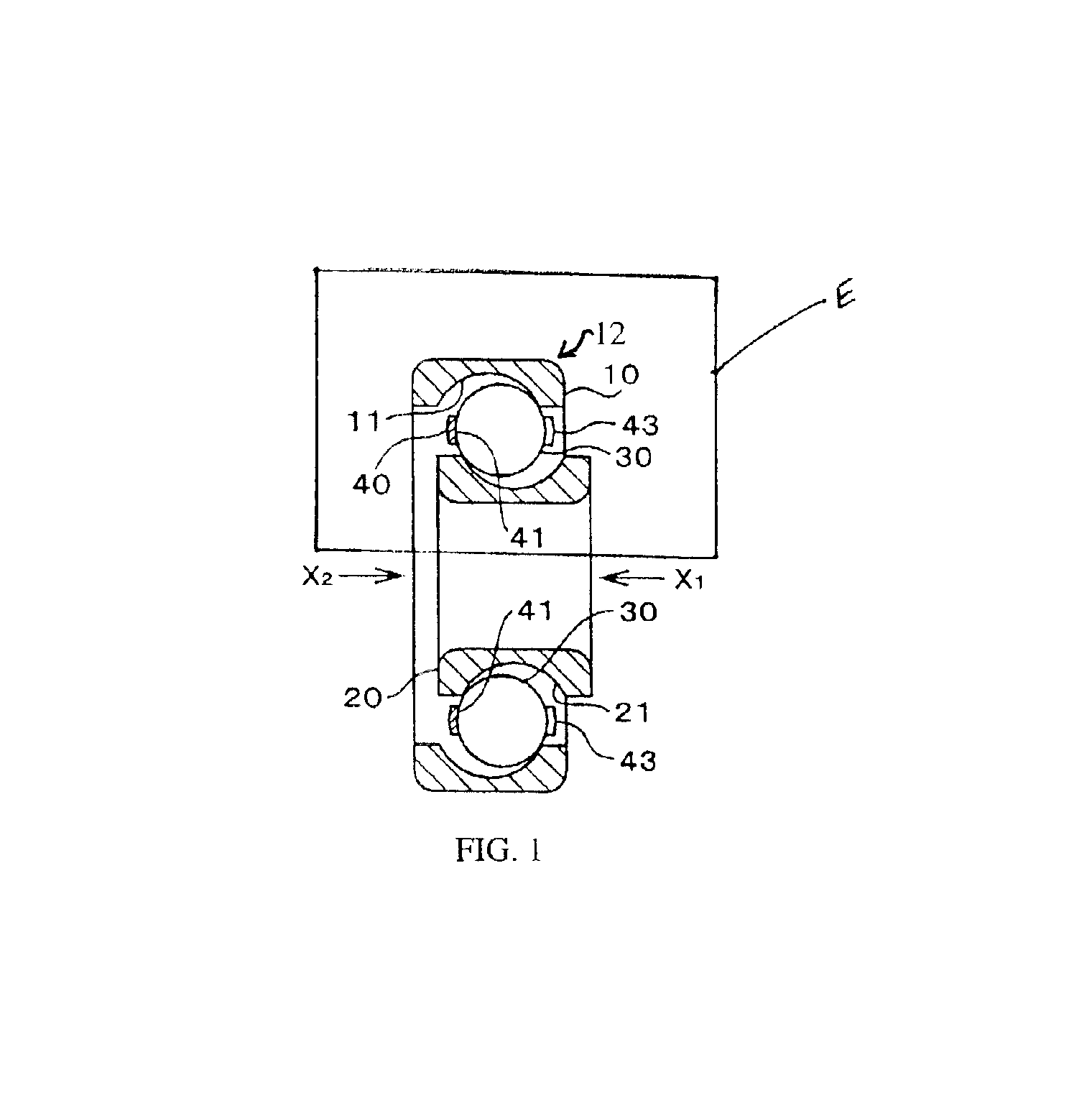
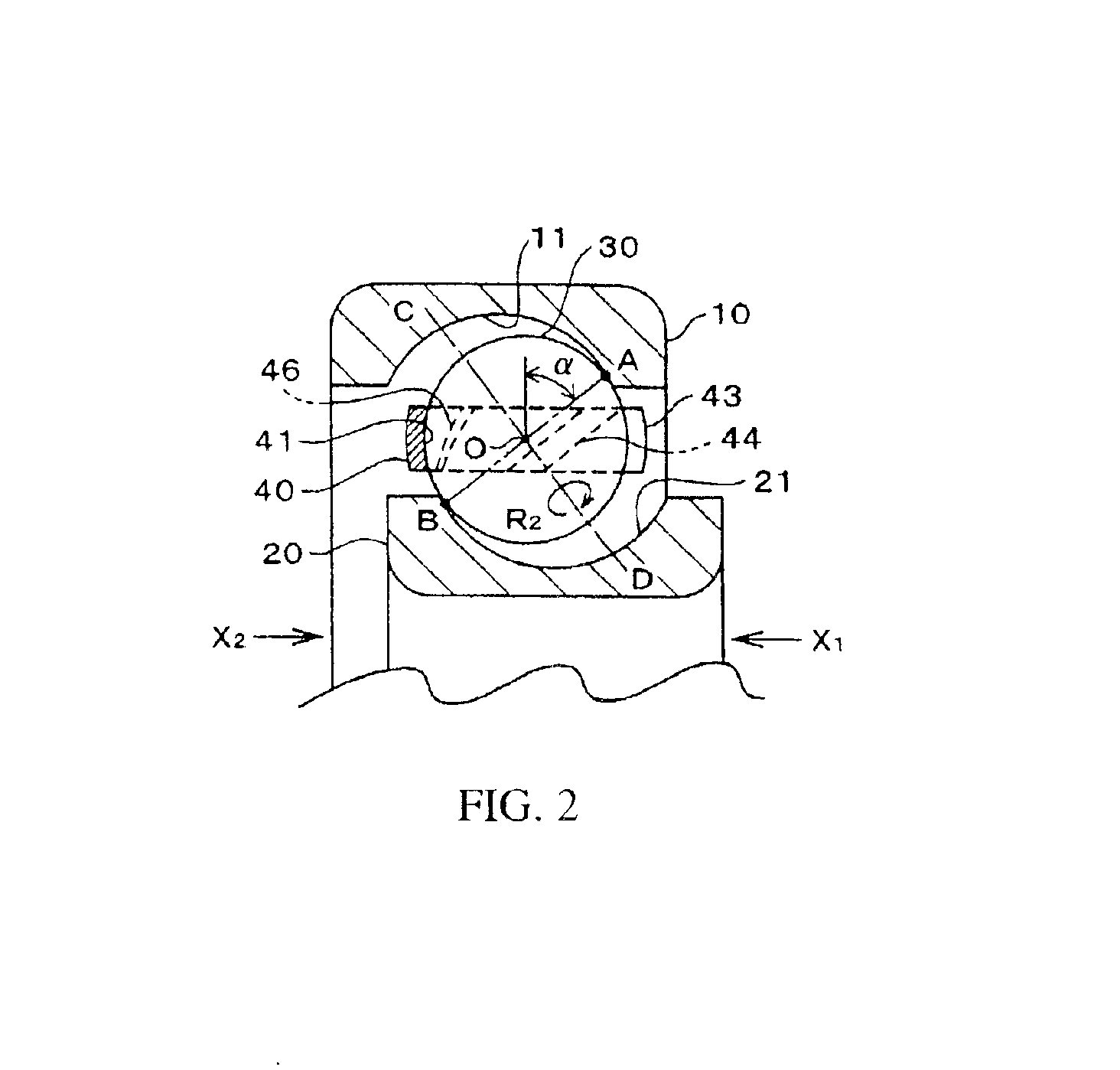
[0029]FIG. 1 depicts a deep channel type radial ball bearing 12 (hereinafter referred to as “bearing”) employing a retainer 40 of the Bearing 12 has an outer ring 10 and an inner ring 20. Running channels 11 and 21 are formed on the mutually opposing orbiting surfaces of outer ring 10 and inner ring 20, respectively. Thus, running channels 11 and 21 are on the inner perimeter surface of outer ring 10 and the outer perimeter surface of inner ring 20 respectively. A specified number of balls 30 are fit into running channels 11 and 21. Retainer 40 having pockets 41 is placed between outer ring 10 and inner ring 20. Each ball 30 is captured in pocket 41. The space between any two adjacent balls 30 is the same. Balls 30 are free to roll within their corresponding pockets 41. Running channels 11 and 21 are arc-shaped, with a diameter somewhat larger than the diameter of balls 30. The larger diameter of running channels 11 and 21 results in a radial gap between the surface of running chan...

second embodiment

[0042]FIG. 7 shows retainer 40 preferably for use when, as seen from the X1 direction, outer ring 10 rotates counterclockwise (R5 direction) and outer ring 10 and inner ring 20 are axially offset, as shown in FIGS. 1 and 2. Balls 30 rolling direction in this case is the R6 direction. Channel 46 is formed in the rolling direction of balls 30 on the inner surface of pocket 41. The lubricating oil flows in this channel 46 and is directed to the outer perimeter surface. Inclined surface 45a of fin 45 receives the lubricating oil and directs it to the vicinity of the pocket's 41 opening on the trailing side of retainer's direction of rotation.

third embodiment

[0043]FIG. 8 shows retainer 40 preferably used when the inner ring 20 rotates in a clockwise direction (R3 direction) as seen from the direction of X1 in FIGS. 1 and 2. In this case, the preload is applied to inner ring 20 in the X2 direction as shown in FIGS. 1 and 2. Balls 30 roll in the R6 direction. Channel 46 is formed in pocket's 41 inner surface in the rolling direction, and lubricating oil flows in channel 46 and is directed to the inner perimeter surface. Inclined surface 45a of fin 45 receives the lubricating oil from channel 46 and directs it to the vicinity of the opening of pocket 41 on the trailing side of the retainer's direction of rotation.


PUM


Abstract

A deep channel type of radial ball bearing having a retainer. The bearing has an outer ring and an inner ring. Running channels are formed on the mutually opposing orbiting surfaces of the outer ring and inner ring. A specified number of balls are fit into the running channels. The retainer having pockets is placed between the outer ring and the inner ring. Each ball is captured in one of the pockets. A ball contact surface is formed on the inner surface of each edge on the opening side of the pockets. A curved ridge line forms the boundary between the inner surface of the pocket and the contact surface. This curved ridge line that forms the boundary is substantially parallel to the direction of rotation of the balls. A channel is formed at the bottom surface of the pocket. The channel extends from the inner perimeter to the outer perimeter of the retainer. The lubricating oil on the bottom surface of the pocket flows through the channel by virtue of the rolling of the balls and is guided to the outer perimeter side. A triangle-shaped fin having an inclined surface is integrally formed between the adjacent pockets on the outer perimeter surface. The inclined surface is formed on the trailing side of pocket with respect to the retainer direction of rotation. Lubricating oil directed from the above-described channel to the outer perimeter surface by the rolling of the ball is received at the inclined surface of the fin and is supplied to the vicinity of the leading edge of the pocket that is located behind the fin by the rotation of the retainer.

Description

CROSS REFERENCE TO RELATED APPLICATION[0001]This application claims priority from the commonly-assigned Japanese Patent Application Number JP 2002-115901 entitled “Radial Ball Bearing Retainer”.BACKGROUND OF THE INVENTION[0002]1. Field of the Invention[0003]The present disclosure relates to low rotational torque radial ball bearings. The bearings of the present invention may be used, for example, in a general purpose motor and motors used in equipment such as data equipment and audio equipment. In particular, the present disclosure relates to retainer for a radial ball bearing having at least one channel to facilitate flow of lubricating oil.[0004]2. Description of the Related Art[0005]FIG. 10 shows a conventional radial ball bearing 100 having an outer ring 102 and an inner ring 104. Running channels (raceways) 106 and 108 are formed on outer ring 102 and inner ring 104 respectively. Running channel 106 is on the inner surface of outer ring 102. Running channel 108 is on the outer ...

Claims


Application Information

Patent Timeline
Patent Type & Authority Patents(United States)
IPC IPC(8): F16C33/38F16C33/41F16C33/66
CPCF16C33/66F16C33/416F16C19/06F16C33/6629F16C33/6681F16C2380/26
Inventor IDE, FUMIHIKOYAMAMOTO, TAKUYA
Owner MINEBEAMITSUMI INC
Why Eureka
Try Eureka