Clamp nut and collet chuck

Inactive Publication Date: 2005-05-03
BIG ALPHA CO LTD
View PDF17 Cites 10 Cited by
  • Summary
  • Abstract
  • Description
  • Claims
  • Application Information

AI Technical Summary

Benefits of technology

[0020]Since the collet chuck having this configuration includes the clamp nut having the above-described configuration, it is possible to enhance the lubricating property of the sliding surfaces of the clamp nut and the collet and to r

Problems solved by technology

However, concerning the collet chuck having this configuration, heavy stress is exerted between the collet and the clamp nut, and seizure tends to occur.
Accordingly, it is difficult to maintain tool-mounting accuracy.
However, concerning the collet chuck provided with the thrust ball or the taper roller as the low-friction mechanism, there is a

Method used


Image

  • Clamp nut and collet chuck
  • Clamp nut and collet chuck
  • Clamp nut and collet chuck

Examples


embodiment 1

(Embodiment 1)

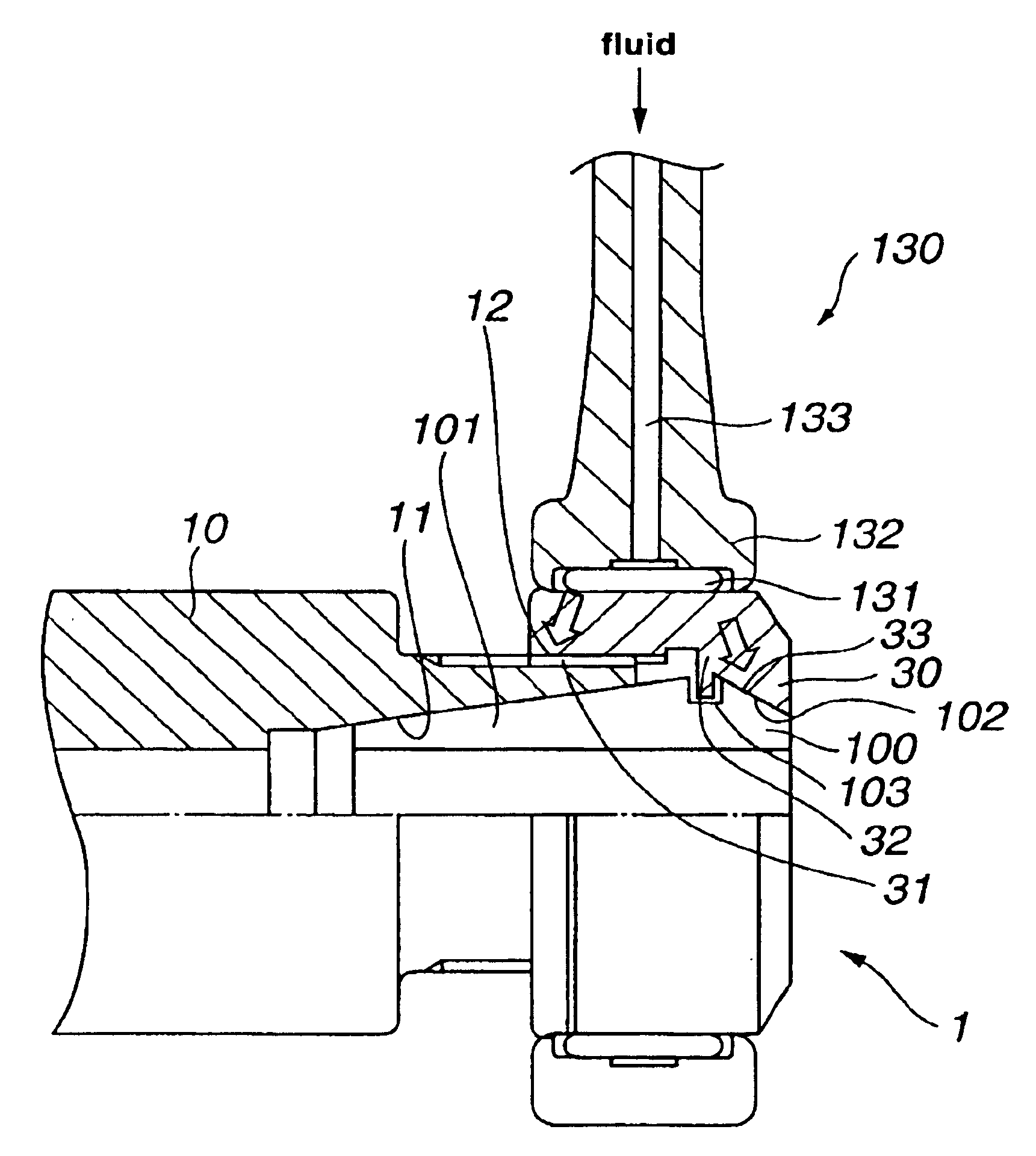
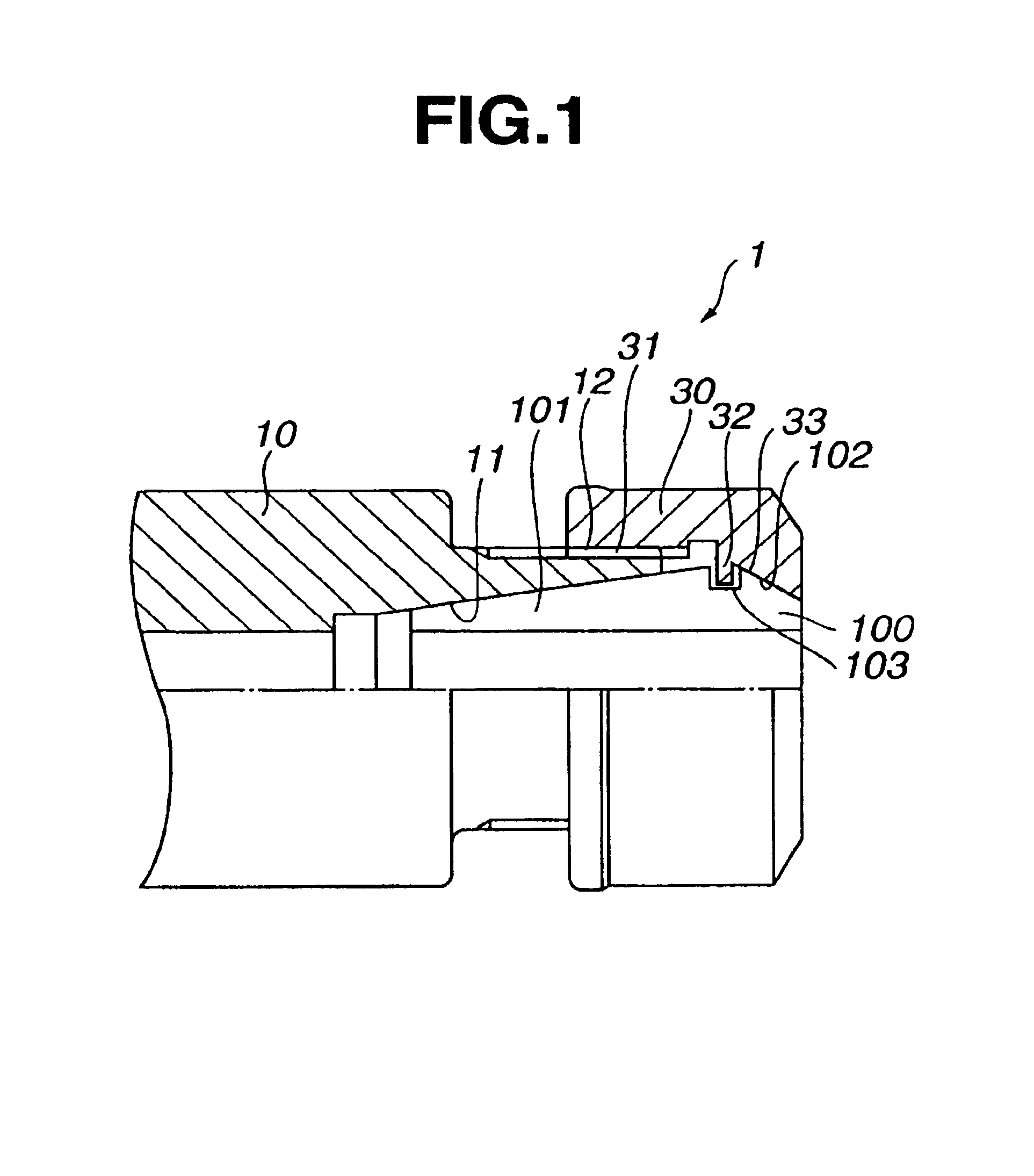
[0032]FIG. 1 is a partially sectional view of a collet chuck with a clamp nut according to Embodiment 1 of this invention.

[0033]A collet chuck 1 of Embodiment 1 comprises a collet chuck body 10 and a clamp nut 30 mounted on the collet chuck body 10.

[0034]In the collet chuck body 10 is formed a tapered hole 11, the diameter of which becomes gradually smaller from its top-end side toward its base-end side. A tapered collet 100 is inserted in this tapered hole 11. On the outer surface of the collet chuck body 10 on the top-end side is formed a screw part 12 for engaging with a screw part 31 formed on the inner surface of a clamp nut 30 as described below. As the clamp nut 30 externally engages with and clamps the collet chuck body 10, the collet chuck body 10 contracts the diameter of the tapered collet 100 inserted in the tapered hole 11, thereby firmly securing a tool held in the tapered collet 100.

[0035]This tapered collet 100 has a plurality of slots 101 cut in the ax...

embodiment 2

(Embodiment 2)

[0045]A clamp nut and a collet chuck with the clamp nut according to Embodiment 2 of this invention are hereinafter explained with reference to the relevant drawings. In Embodiment 2, elements similar to those of the collet chuck 1 described in Embodiment 1 are given the same reference numerals as in Embodiment 1, and any detailed description thereof is omitted.

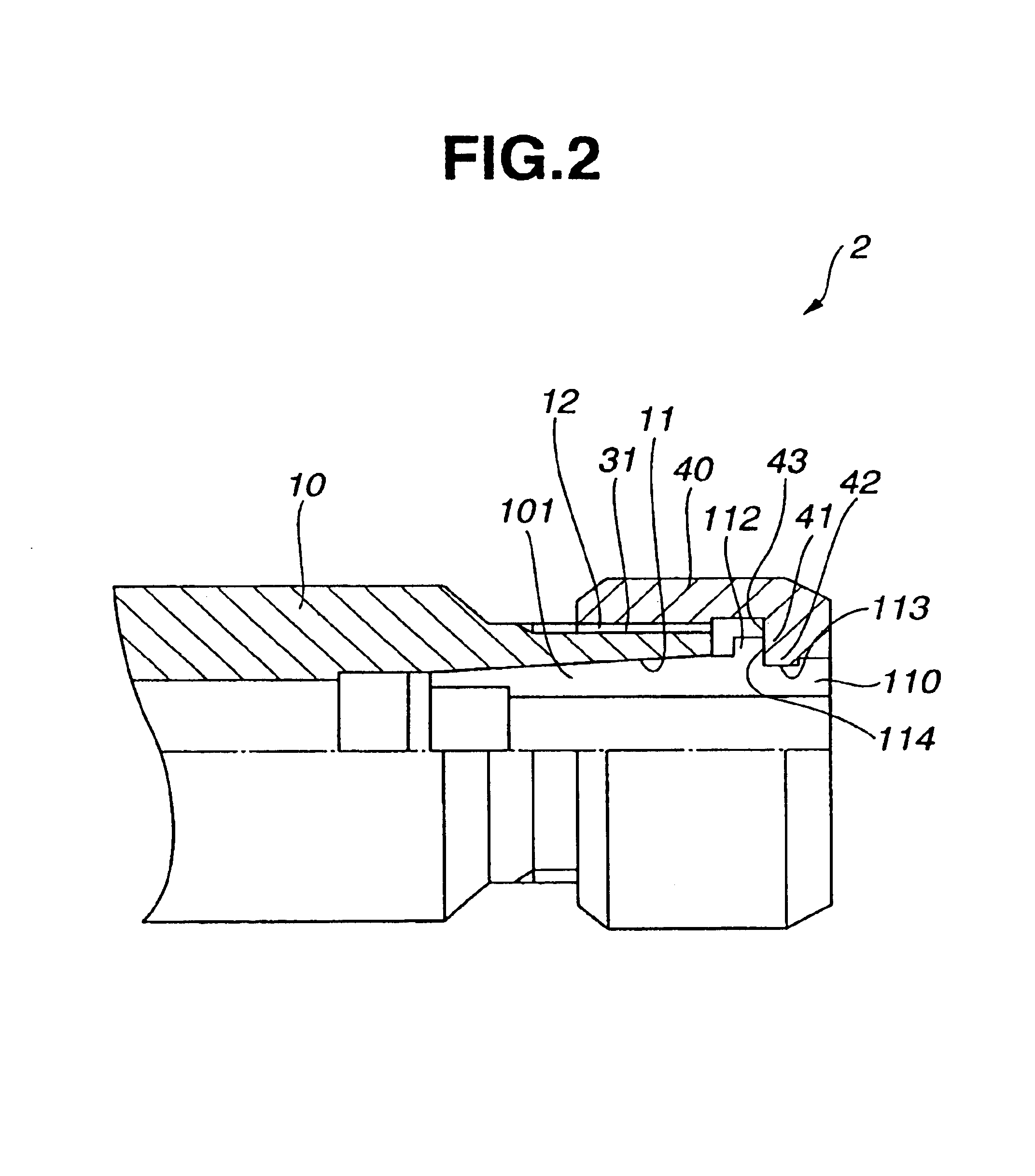
[0046]FIG. 2 is a partially sectional view of the collet chuck with the clamp nut according to Embodiment 2 of this invention.

[0047]As shown in FIG. 2, the main difference between a collet chuck 2 of Embodiment 2 and the collet chuck 1 of Embodiment 1 is the shape of a tapered collet 110 and the shape of a clamp nut 40.

[0048]Specifically, the tapered collet 110 of Embodiment 2 comprises a plurality of slots 101 cut in the axial direction alternately from the top-end side and from the base-end side, and a flange 112 is formed on the outer surface of the tapered collet 110 slightly off the top end thereof closer t...

embodiment 3

(Embodiment 3)

[0055]A clamp nut and a collet chuck with the clamp nut according to Embodiment 3 of this invention are hereinafter explained with reference to the relevant drawings. In Embodiment 3, elements similar to those of the collet chucks described in the aforementioned embodiments are given the same reference numerals as in the aforementioned embodiments, and any detailed description thereof is omitted.

[0056]FIG. 3 is a partially sectional view of the collet chuck with the clamp nut according to Embodiment 3 of this invention.

[0057]As shown in FIG. 3, the main difference between a collet chuck 3 of Embodiment 3 and the collet chuck 1 of Embodiment 1 is the shape of a clamp nut 50. Specifically, the clamp nut 50 of Embodiment 3 comprises a nut body 51 and a thrust ring 52 provided between a tapered collet 100 and the nut body 51.

[0058]On the inner surface of the nut body 51 on the base-end side is formed a screw part 31 for engaging with a screw part 12 formed on the outer sur...


PUM

PropertyMeasurementUnit
Timeaaaaaaaaaa
Durabilityaaaaaaaaaa
Friction coefficientaaaaaaaaaa

Abstract

The present invention enhances the lubricating property of the sliding surfaces of a clamp nut and a collet, reduces a friction coefficient, prevents the occurrence of seizure, and enhances durability. Accordingly, it is possible to rotate the clamp nut and the collet without causing vibrations due to imbalance. Moreover, this invention provides a clamp nut that can maintain tool-mounting accuracy for a long period of time even in the case of high-speed rotation, and also provides a collet chuck including such clamp nut. Concerning the clamp nut which is mounted on a collet chuck body for holding tools in the collet and which clamps the collet chuck body and the collet together, at least a part of the clamp nut which comes in contact with the collet is made of oil-bearing metal.

Description

BACKGROUND OF THE INVENTION[0001]1. Field of the Invention[0002]The present invention relates to a clamp nut which is mounted on a collet chuck body for holding tools in a collet, and which clamps the collet chuck body and the collet together. This invention also relates to a collet chuck including this clamp nut.[0003]2. Description of the Related Art[0004]A collet chuck has been used which is designed to hold a cutting tool by causing a collet to engage with a tapered hole in the top end of the chuck body provided on a machine tool and by using a clamp nut to clamp the cutting tool mounted on the collet, thereby causing the diameter of the collet to contract.[0005]There is one type of such collet chuck in which a thrust ring and a nut body are integrated with each other so that the diameter of the clamp nut is made smaller in order to attain satisfactory balance. However, concerning the collet chuck having this configuration, heavy stress is exerted between the collet and the clam...

Claims


Application Information

Patent Timeline
IPC IPC(8): B23B31/20B23B31/00
CPCB23B31/201B23B2250/12Y10T279/17512Y10T279/17538Y10T279/17299B23B2260/106B23B31/20125B23B2231/24
Inventor KOMINE, TSUYOSHI
Owner BIG ALPHA CO LTD
Why Eureka
Try Eureka