Vane Pump

A vane pump and vane technology, used in pumps, pump components, rotary piston pumps, etc., can solve the problems of high vane friction coefficient, long heat treatment time, large wear damage, etc., and achieve low friction coefficient and improved wear resistance. , The effect of improving wear resistance

Inactive Publication Date: 2014-09-10
LG ELECTRONICS INC
View PDF4 Cites 10 Cited by
  • Summary
  • Abstract
  • Description
  • Claims
  • Application Information

AI Technical Summary

Problems solved by technology

However, due to the low workability of the stator and the rotor, not only the heat treatment time is long and the manufacturing cost is high, but also the damage caused by abrasion is large due to the high coefficient of friction with the blades.

Method used


Image

  • Vane Pump
  • Vane Pump
  • Vane Pump

Examples


Embodiment Construction

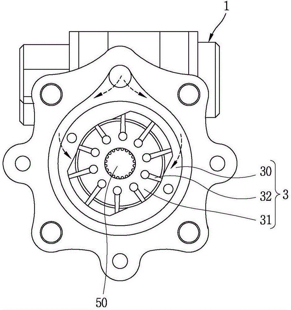
[0033] Hereinafter, embodiments of the vane pump according to the present invention will be described in detail with reference to the drawings. Here, the present invention does not relate to the form of the components constituting the vane pump, but relates to the materials of the rotor, vane, and stator, so it is applicable to a vane pump having any form of the rotor, vane, and stator. In the following description, based on the above figure 1 The above-described vane pump will be described.

[0034] First, the manufacturing process of the rotor in the above-mentioned embodiment will be described.

[0035] (1) Melting

[0036] Contains C: 3.5-3.9%, Si: 2.2-3.0%, Mn: 0.1-0.5%, S≤0.02%, P≤0.04%, Cu: 0.1-0.5%, Mo: 0.1-0.3%, Mg by weight : 0.02 to 0.05% and Re: 0.01 to 0.04%, the elements are mixed in an appropriate proportion, heated by an electric furnace, etc., and then smelted.

[0037] (2) Spheroidization treatment and inoculation

[0038] Inoculate the nodulizer and ino...


PUM

PropertyMeasurementUnit
tensile strengthaaaaaaaaaa
hardnessaaaaaaaaaa

Abstract

The invention relates to a vane pump. According to an embodiment of the invention, a vane pump is provided. The vane pump includes: a rotor having a plurality of slots formed on an outer circumferential surface thereof; vanes slidably inserted into each of the slots; and a cam ring having the rotor therein and having a inner circumferential surface in contact with an end portion of the vane, wherein the rotor is formed of nodular graphite cast iron, the vanes are formed of high speed tool steel, and the cam ring is formed of alloy cast iron.

Description

technical field [0001] The present invention relates to vane pumps, and more particularly, to vane pumps used as steering pumps for automobiles. Background technique [0002] At present, in order to increase the steering force of an automobile steering device, various devices are used, and in the case of a hydraulic steering device, a power steering pump for supplying hydraulic pressure is used. As such a power steering pump, various types of pumps can be used, but a vane pump having high efficiency, small size and weight, and small vibration is generally used. [0003] figure 1 A cross-sectional view of an example of such a vane pump is briefly shown, wherein the above-mentioned vane pump includes a main body 1 and a pump core package 3 built in the above-mentioned main body 1, and the above-mentioned pump core package 3 includes: a rotor 31, which is rotatable and a stator 30 in which the above-mentioned rotor 31 is built. Furthermore, a plurality of slots are formed in...

Claims


Application Information

Patent Timeline
Patent Type & Authority Applications(China)
IPC IPC(8): F04C2/344C22C37/04C22C37/10C22C38/24C21D1/20
CPCC22C37/04F01C21/0809F04C18/356F04C2230/21F04C18/10F04C2/3446F04C2240/20F05C2201/0442F05C2201/0448F04C18/00F04C29/02F04C29/12F05C2201/0439F05C2203/0808
Inventor 朴载奉
Owner LG ELECTRONICS INC
Why Eureka
Try Eureka