Isothermal fixed bed reactor loading catalyst among heat exchange tubes

A fixed-bed reactor and catalyst technology, applied in the direction of chemical instruments and methods, chemical/physical processes, etc., can solve the problems of small size, catalyst deactivation, etc., and achieve the effect of not easy side reactions and large loading capacity

Active Publication Date: 2014-10-15
SHANGHAI INT ENG CONSULTING
View PDF8 Cites 12 Cited by
  • Summary
  • Abstract
  • Description
  • Claims
  • Application Information

AI Technical Summary

Problems solved by technology

For example, CN101254442A discloses a pressurized catalytic method for exothermic reaction, which mainly adopts a centrifugal radial flow reactor from inside to outside. Although the catalyst loading is large, the amount of catalyst that the radial flow reaction gas flows through Not big, if the gas purification is not good, it is more likely to cause catalyst deactivation

Method used


Image

  • Isothermal fixed bed reactor loading catalyst among heat exchange tubes
  • Isothermal fixed bed reactor loading catalyst among heat exchange tubes
  • Isothermal fixed bed reactor loading catalyst among heat exchange tubes

Examples


Embodiment 1

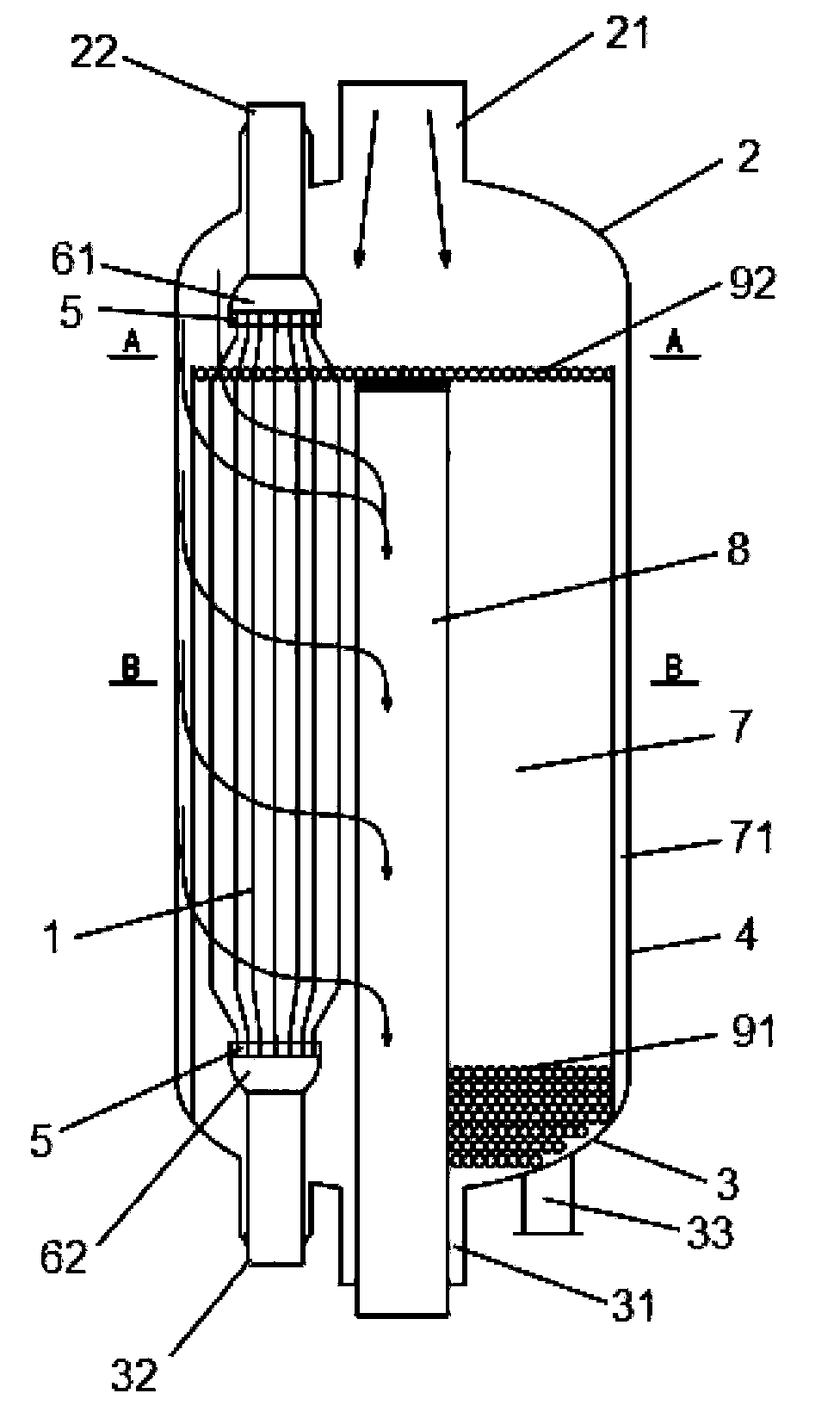
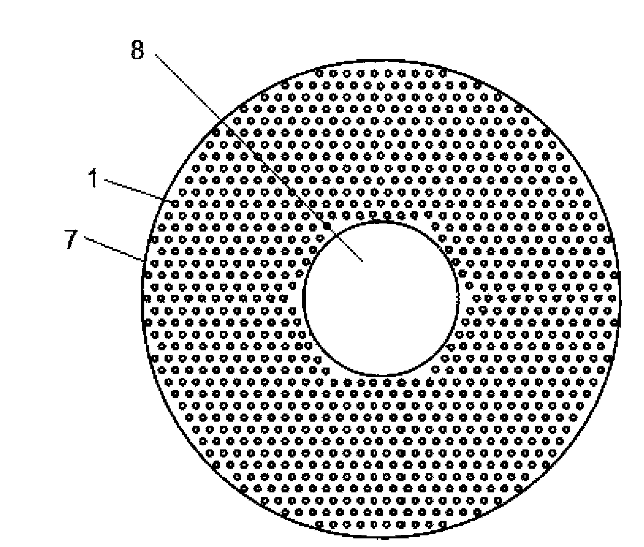
[0051] refer to figure 1 , 2 and 3, an isothermal fixed-bed reactor in which catalyst is installed between heat exchange tubes, is an axial radial reactor, including a pressure-bearing shell, a heat-exchange tube 1 installed in the pressure-bearing shell, and a catalyst cylinder.

[0052] The pressure shell includes an upper head 2, a lower head 3, and a cylinder 4; the upper head 2 is welded to the top of the cylinder 4, and the upper head 2 is provided with a gas inlet 21 and a heat exchange medium outlet 22; The lower head 3 is welded to the bottom of the cylinder body 4 , and the lower head 3 is provided with a gas outlet 31 , a heat exchange medium inlet 32 ​​and a catalyst discharge port 33 .

[0053] The two ends of the heat exchange tube 1 are closed and welded to the tube plate 5 respectively, and communicate with the upper tube box 61 and the lower tube box 62 respectively, the upper tube box 61 is connected with the heat exchange medium outlet 22, and the lower tub...

Embodiment 2

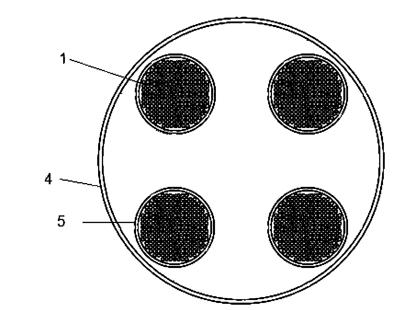
[0059] refer to Figure 4 , an isothermal fixed-bed reactor in which catalyst is installed between heat exchange tubes is an axial reactor comprising a pressure-bearing shell, a heat-exchange tube 1 installed in the pressure-bearing shell and a catalyst cylinder.

[0060] The pressure shell includes an upper head 2, a lower head 3, and a cylinder 4; the upper head 2 is welded to the top of the cylinder 4, and the upper head 2 is provided with a gas inlet 21 and a heat exchange medium outlet 22; The lower head 3 is welded to the bottom of the cylinder body 4 , and the lower head 3 is provided with a gas outlet 31 , a heat exchange medium inlet 32 ​​and a catalyst discharge port 33 .

[0061] Both ends of the heat exchange tube 1 are closed and welded to the tube plate 5 respectively, and communicate with the upper tube box 61 and the lower tube box 62 respectively, the upper tube box 61 is connected with the heat exchange medium outlet 22, and the lower tube box 62 is connected...


PUM


Abstract

The invention provides an isothermal fixed bed reactor loading a catalyst among heat exchange tubes, and the isothermal fixed bed reactor comprises a pressure-bearingg casing, the plurality of heat exchange tubes installed in the pressure-bearing casing, and the catalyst; gaps among the plurality of heat exchange tubes form a catalyst filling zone, and a gas inlet, the gaps among the plurality of heat exchange tubes and a gas outlet form a gas channel. The isothermal fixed bed reactor loads the catalyst among the plurality of heat exchange tubes, the catalyst loading quantity is large; the heat exchange tubes can quickly remove the reaction heat, the whole bed basically reaches the even temperature effect and is free of excess temperature and occurrence of side reactions, and the isothermal fixed bed reactor enables a reaction gas to axially radially flow in the bed, can maximize the use of the and can use a more active small particle catalyst.

Description

technical field [0001] The present invention relates to an isothermal fixed-bed reactor, in particular to an isothermal fixed-bed reactor in which a catalyst is installed between heat exchange tubes. The isothermal fixed-bed reactor can be an axial radial reactor, a pure axial reactor or a Pure radial reactor. Background technique [0002] With the development of chemical production, in order to adapt to different heat transfer requirements and heat transfer methods, a variety of fixed-bed reactor structures have emerged, among which gaseous reaction materials are used to react through a bed composed of solid catalysts. The gas-solid phase catalytic reactor is the most widely used in chemical production. [0003] Fixed-bed reactors are mainly divided into two categories: adiabatic and heat-exchange based on the reaction principle. [0004] The adiabatic fixed bed reactor has a simple structure and is widely used. However, in actual operation, the adiabatic reactor cannot ...

Claims


Application Information

Patent Timeline
Patent Type & Authority Applications(China)
IPC IPC(8): B01J8/02
Inventor 杨震东刘磊顾鹤燕张西原
Owner SHANGHAI INT ENG CONSULTING
Why Eureka
Try Eureka