Large-size high-speed invisible flying saucer

A flying saucer and disc-shaped technology, applied in aircraft, aircraft control, aircraft parts, etc., can solve the problems of invisibility, poor vertical maneuverability, and inability to load loads, etc., to achieve mature manufacturing technology, improve vertical maneuverability, and increase speed and mobility effects

Inactive Publication Date: 2016-02-10
周彦辉
View PDF0 Cites 13 Cited by
  • Summary
  • Abstract
  • Description
  • Claims
  • Application Information

AI Technical Summary

Problems solved by technology

[0011] 2. The cabin is small and cannot carry more loads
[0012] 3. Slow speed and low altitude
[0013] 4. Poor vertical maneuverability and cannot be invisible
The aircraft cannot perform vertical jump maneuvers, and the high-temperature gas emitted by the engine is easily detected by infrared detection equipment, making it impossible to be invisible

Method used


Image

  • Large-size high-speed invisible flying saucer
  • Large-size high-speed invisible flying saucer
  • Large-size high-speed invisible flying saucer

Examples


Embodiment Construction

[0053] Below in conjunction with accompanying drawing and embodiment the present invention will be further described:

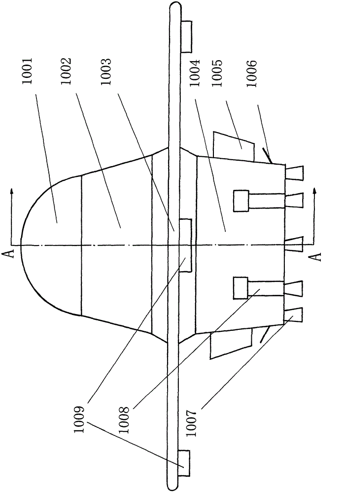
[0054] figure 1 It is the front view of the flying saucer of the present invention, as shown in the figure, the flying saucer is composed of cockpit 1001, passenger compartment 1002, disc-shaped wing 1003, equipment compartment 1004, fixed wing surface 1005, infrared emitter 1006, vector engine 1007, landing gear 1008, rotary motor 1009, etc. constitute.

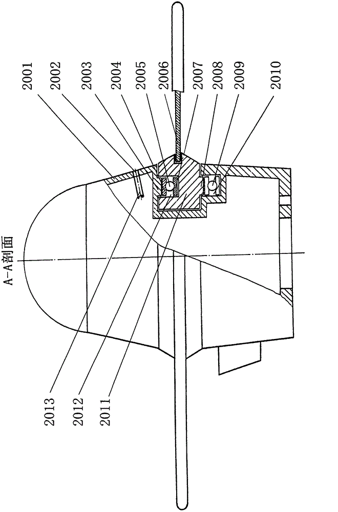
[0055] figure 2 It is a schematic view of the partial structure of the vertical section of the embodiment of the present invention, showing the internal conditions of the rolling contact between the nacelle and the disc-shaped wing through thrust ball bearings. Thrust ball bearing upper ring 2004, thrust ball bearing steel ball 2005, blade 2006, thrust ball bearing lower ring 2007, wheel hub annular flange 2008, lower thrust ball bearing 2009, equipment cabin annular groove 2010, wheel hub 2011, wheel hu...


PUM


Abstract

The invention discloses a flying saucer and two smoke- and fire-free engines. The flying saucer is composed of a cabin and a disk which rotates round the cabin. The disk includes a disk-shaped wing and a rotary engine. The cabin includes a driving cabin, a passenger cabin and a device cabin. The rotary engine sucks air which is mixed with water, and then the mixture is jetted out horizontally through jet tubes installed on the edge of the disk according to the sprayer principle, so that a generated reactive force enables the disk to rotate at a high speed, thereby generating an upward raising force on the disk. Four fixing wings are installed outside the device cabin to eliminate reverse rotation of the cabin. A vector engine and a diesel power generating set are installed in the device cabin under the disk. The vector engine sucks large amount of air through an air inlet duct in the passenger cabin to form vacuum above the passenger cabin, which enables air pressure difference between an upper surface and a lower surface of the disk to be increased, thereby generating a huge raising force. The sucked air is compressed to form high-pressure gas which is discharged into vector jet tubes and is jetted out, wherein the directions and the angles of the vector jet tubes are adjustable to generate pushing forces in different directions, thereby achieving maneuvering flight of the flying saucer.

Description

technical field [0001] The invention relates to the field of aviation, in particular to the technical field of manufacturing a saucer-shaped aircraft. Background technique [0002] According to the information disclosed in recent years, during the Second World War, Nazi Germany secretly developed a saucer-shaped aircraft, and has already produced a flying prototype "Belongcai Disc". [0003] After the end of World War II, the Americans successively manufactured a variety of saucer-shaped aircraft based on the seized Nazi flying saucer manufacturing technical data. The more famous one is the V-173 propeller-powered aircraft; in addition, there is the AVROCAR which uses the turbofan engine as the power. [0004] In 1955, the Hill Corporation of the United States developed a disc-shaped aircraft called the VZ-1 flying platform, with a flight speed of 24 kilometers per hour. [0005] In 1980, Moore Corporation of the United States developed a two-seater XM-4 flying disc with a...

Claims


Application Information

Patent Timeline
Patent Type & Authority Applications(China)
IPC IPC(8): B64C39/06B64C29/00B64C15/14B64D27/16
Inventor 周彦辉
Owner 周彦辉
Why Eureka
Try Eureka