Cradle head

A gimbal and roll axis technology, applied in the field of aircraft, can solve the problems of small rotational inertia of the pan axis, unable to achieve stability enhancement, etc., and achieve the effect of light overall weight

Inactive Publication Date: 2016-05-25
ZEROTECH (BEIJING) INTELLIGENCE TECH CO LTD
View PDF13 Cites 10 Cited by
  • Summary
  • Abstract
  • Description
  • Claims
  • Application Information

AI Technical Summary

Problems solved by technology

[0004] The purpose of the present invention is to propose a cloud platform, which can solve the problem that the rotational inertia of the yaw axis is small and cannot achieve stability enhancement.

Method used


Image

  • Cradle head
  • Cradle head

Examples


Embodiment 1

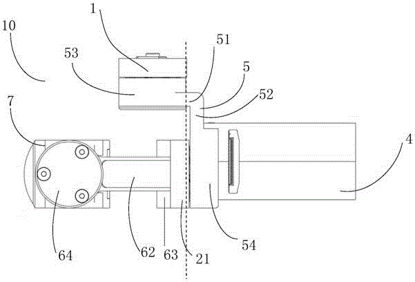
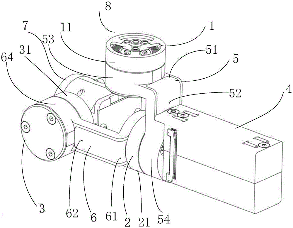
[0022] see figure 1 , a kind of cloud platform 8 is provided in the present embodiment, and this platform comprises yaw axis motor 1, roll axis motor 2, pitch axis motor 3 and controller 4, and wherein the top of yaw axis motor 1 is provided with connected with aircraft A connecting platform (not shown in the figure), the panning axis motor 1 and the rolling axis motor 2 are connected through the first connecting axis arm 5, the rolling axis motor 2 and the pitching axis motor 3 are connected through the second connecting axis arm 6, and the controller 4 It is located under the yaw axis motor 1 or on the aircraft.

[0023] When the controller was positioned under the yaw axis motor 1, the roll axis motor stator (not shown) was connected to the first connecting shaft arm 5, and its rolling axis motor rotor 21 was connected to the second connecting shaft arm 6; The shaft motor stator (not shown) is connected to the second connecting shaft arm 6 , and the imaging device 7 is pro...

Embodiment 2

[0032] The differences between this embodiment and Embodiment 1 are:

[0033] In this embodiment, the controller 4 is located in front of the roll axis motor 2 , and the controller 4 is fixed on the roll axis motor 2 or the second connecting arm 6 .

[0034] In this embodiment, the front of the roll axis motor 2 specifically refers to the front of the roll axis motor rotor 22; at the same time, in order to meet the above structural layout, the length of the first connecting shaft arm 5 in this embodiment should be greater than that of the first connecting shaft arm 5 in Embodiment 1. One is the length of the connecting shaft arm 5 .

[0035] The rest of the structure in this embodiment is the same as that in Embodiment 1, so it will not be repeated here.

Embodiment 3

[0037] The differences between this embodiment and Embodiment 1 are:

[0038] The controller 4 is fixedly arranged behind the pitch axis motor 3 . That is, the imaging device and the controller 4 are respectively located at the front and rear positions of the pitch axis motor 3 , and the controller 4 will not rotate with the pitch axis motor 3 during the rotation of the imaging device 7 driven by the pitch axis motor 3 . At the same time, the length of the first connecting shaft arm 5 in this embodiment is greater than that of the first connecting shaft arm 5 in Embodiment 1, so as to prevent the whole aircraft from being unstable due to the deviation of the center of mass caused by the weight change.

[0039] The rest of the structure in this embodiment is the same as that in Embodiment 1, so it will not be repeated here.


PUM


Abstract

The invention relates to the technical field of aircrafts, in particular to a cradle head used for carrying an imaging device on an aircraft. The cradle head comprises a course shaft motor, a transverse rolling shaft motor, a pitch shaft motor and a controller. The course shaft motor and the transverse rolling shaft motor are connected through a first connecting shaft arm. The transverse rolling shaft motor and the pitch shaft motor are connected through a second connecting shaft arm. The controller is located below the course shaft motor or on the aircraft. According to the cradle head, since the controller is arranged below the course shaft motor, the overall mass of a structure below the course shaft motor can be increased; after the mass of the structure below a course shaft is increased, the rotational inertia of the course shaft is increased accordingly, and then the problems that the rotational inertia of the course shaft is small and stability cannot be improved are solved. Meanwhile, the controller is a necessary component of the cloud platform and avoids increase of the overall mass of the cradle head while increasing the overall mass of the structure below the course shaft motor, thereby further ensuring low overall mass of the cradle head.

Description

technical field [0001] The invention relates to the technical field of aircraft, in particular to a pan-tilt for mounting an imaging device on an aircraft. Background technique [0002] A common UAV airborne platform refers to a supporting workbench for installing an imaging device, which can be a video camera or a camera. The purpose of imaging the target with the lens of the imaging device is realized by adjusting the pan / tilt. The panning axis motors on the gimbal are mostly reverse-mounted, while the roll-axis motors and pitch-axis motors are front-mounted. The so-called reverse installation means that the stator part of the motor is connected to the rotating shaft arm, and the rotor part of the motor is connected to the fixed shaft arm, while the positive installation is the opposite of the reverse installation. [0003] With the development of technology, the gimbal gradually develops in the direction of small size, light weight, and low cost. However, when the gimba...

Claims


Application Information

Patent Timeline
Patent Type & Authority Applications(China)
IPC IPC(8): B64D47/08
CPCB64D47/08
Inventor 孙宏涛任献伟王超刘庚鹏
Owner ZEROTECH (BEIJING) INTELLIGENCE TECH CO LTD
Why Eureka
Try Eureka