Momentum wheel based on disc type structure

A momentum wheel and disc type technology, applied in the field of momentum wheel, can solve the problems of difficulty in applying agile attitude control system, small output torque and specific torque, and insufficiently compact structure, so as to ensure stability and reduce cogging rotation. Moment, compact structure

Inactive Publication Date: 2016-10-26
XI AN JIAOTONG UNIV
View PDF5 Cites 13 Cited by
  • Summary
  • Abstract
  • Description
  • Claims
  • Application Information

AI Technical Summary

Problems solved by technology

Its disadvantages as a momentum wheel are: the structure is not compact enough, it is difficult to apply to occasions that require the size of the momentum wheel; the output torque and specific torque are small, it is difficult to apply to the agile attitude control system that requires high torque

Method used


Image

  • Momentum wheel based on disc type structure
  • Momentum wheel based on disc type structure
  • Momentum wheel based on disc type structure

Examples


Embodiment Construction

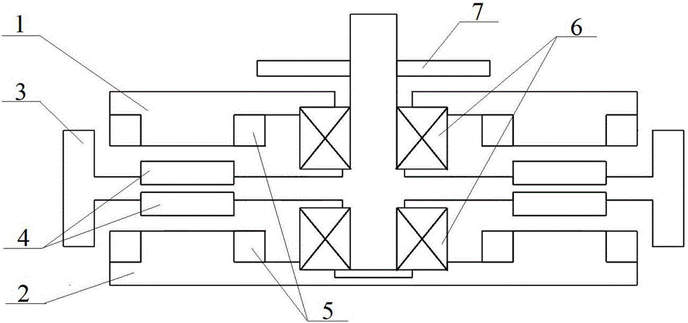
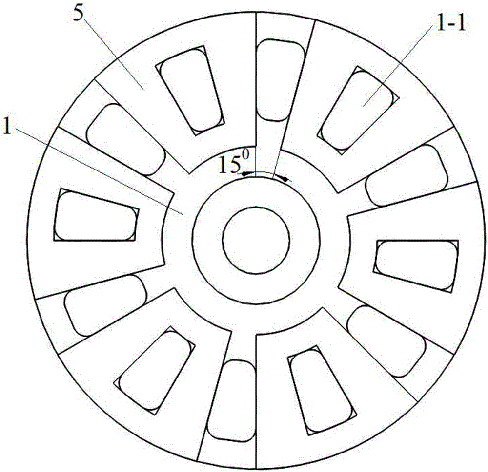
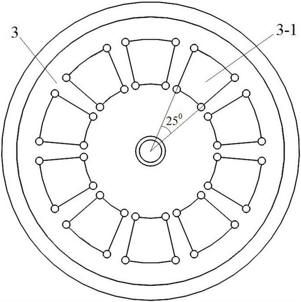
[0022] Combine below figure 1 , figure 2 , image 3 The present invention is further described in detail with specific embodiments.

[0023] Such as figure 1 , figure 2 with image 3 As shown, a momentum wheel based on a disc structure of the present invention includes a lower stator 2 and an upper stator 1. The outer rings of two bearings 6 are respectively fixed on the upper stator 1 and the lower stator 2. The upper stator 1 and the lower stator An air gap is formed between the stators 2 and a rotor 3 is arranged in the air gap. The middle part of the rotor 3 is the middle shaft of the motor. The two bearings 6 are respectively sleeved on the middle shaft of the motor. The lower planes are respectively provided with sector ring grooves 3-1, and permanent magnets 4 are fixed in the sector ring grooves 3-1. The magnetizing directions of the upper and lower layers of permanent magnets 4 are axial and the same, with N poles and S poles alternately arranged The upper stator 1 a...


PUM


Abstract

The invention relates to a momentum wheel based on a disc type structure. The momentum wheel comprises a lower layer stator and an upper layer stator, wherein the upper layer stator and the lower layer stator are fixed in parallel; an air gap is formed between the upper layer stator and the lower layer stator; a rotor is arranged in the air gap; a mass block is arranged at the outer side of the rotor; the upper and lower planes of the inside are provided with annular sector grooves in the radial direction; a permanent magnet is fixed in each groove; the magnetizing directions of the permanent magnets at the upper and lower layers are identical; the N poles and the S poles are alternately arranged; stator tooth grooves are formed in the upper layer stator and the lower layer stator; a coil is wound in each stator groove; the stators are fixed with the outer sides of bearings; the center of the rotor is a motor middle shaft; the bearings sheath the middle shaft; and the top of the middle shaft is provided with a photoelectric encoder. The momentum wheel has the advantages that in the moving process, the input is a three-phase power supply; a permanent magnet motor of an axial magnetic field structure is used, the momentum wheel can output great torque; by using the disc type structure of the momentum wheel, the structure of the momentum wheel is compact, and the axial size of the momentum wheel is effectively reduced; fractional-slot structure windings are used, so that the tooth groove torque of the momentum wheel can be effectively reduced, and the movement of the momentum wheel is smooth and stable; and meanwhile, the photoelectric encoder is used, so that the rotation condition of the momentum wheel can be precisely measured.

Description

Technical field [0001] The invention relates to the technical field of momentum wheels, in particular to a momentum wheel based on a disc structure. Background technique [0002] The existing momentum wheel mainly uses a radial magnetic field permanent magnet motor as the driving motor of the momentum wheel. The working principle of these radial magnetic field permanent magnet motors is: the stator is an iron core with coil windings wound on it, and three-phase sine or Square wave voltage, the phase difference between the three phases is 120 degrees. The rotor is a permanent magnet fixed on the rotor tray, with N poles and S poles arranged alternately. When working, the three-phase power supply is connected, and the energized coil generates a rotating magnetic field in the air gap between the stator and the rotor to drive the rotor to rotate. Its shortcomings as a momentum wheel are: the structure is not compact enough to be suitable for occasions where the size of the momentum...

Claims


Application Information

Patent Timeline
Patent Type & Authority Applications(China)
IPC IPC(8): H02K16/04H02K7/02H02K11/21
CPCH02K7/02H02K16/04Y02E60/16
Inventor 孙剑郭彦昊
Owner XI AN JIAOTONG UNIV
Why Eureka
Try Eureka