Wireless communication apparatus and information processing terminal apparatus with a wireless application

a technology of information processing terminal and wireless application, which is applied in the direction of electrical equipment, multiple-port networks, coupling devices, etc., can solve the problems of linearity deterioration, loss on the output side, general deterioration of system linearity, etc., to improve the overall performance of wireless application, reduce total transmission loss, and improve individual circuit performance

Inactive Publication Date: 2009-12-22
SHARP KK
View PDF17 Cites 0 Cited by
  • Summary
  • Abstract
  • Description
  • Claims
  • Application Information

AI Technical Summary

Benefits of technology

[0019]An object of the present invention is to provide a wireless communications apparatus, and an information processing terminal apparatus with a wireless application ensuring improvement of overall performance of the wireless application without reducing the total transmission loss or improving the performance of individual circuits.

Problems solved by technology

Further, in a system that requires linearity, the linearity of the system generally deteriorates as the output power of the active circuit is increased.
Thus, in view of giving the same output power at the antenna terminal, the loss on the output side deteriorates the linearity of the system.

Method used


Image

  • Wireless communication apparatus and information processing terminal apparatus with a wireless application
  • Wireless communication apparatus and information processing terminal apparatus with a wireless application
  • Wireless communication apparatus and information processing terminal apparatus with a wireless application

Examples


first embodiment

[0042]Referring to FIG. 1, one embodiment of the present invention is described below. While the invention is susceptible to various modifications and alternative forms, specific embodiments thereof will be described below by way of a wireless LAN card and a wireless LAN apparatus as exemplary forms of a wireless communications apparatus according to the present invention. It should be understood, however, that they are not intended to limit the invention to the particular forms disclosed, but on the contrary, the invention is also applicable to other apparatuses, including a mobile phone, for example.

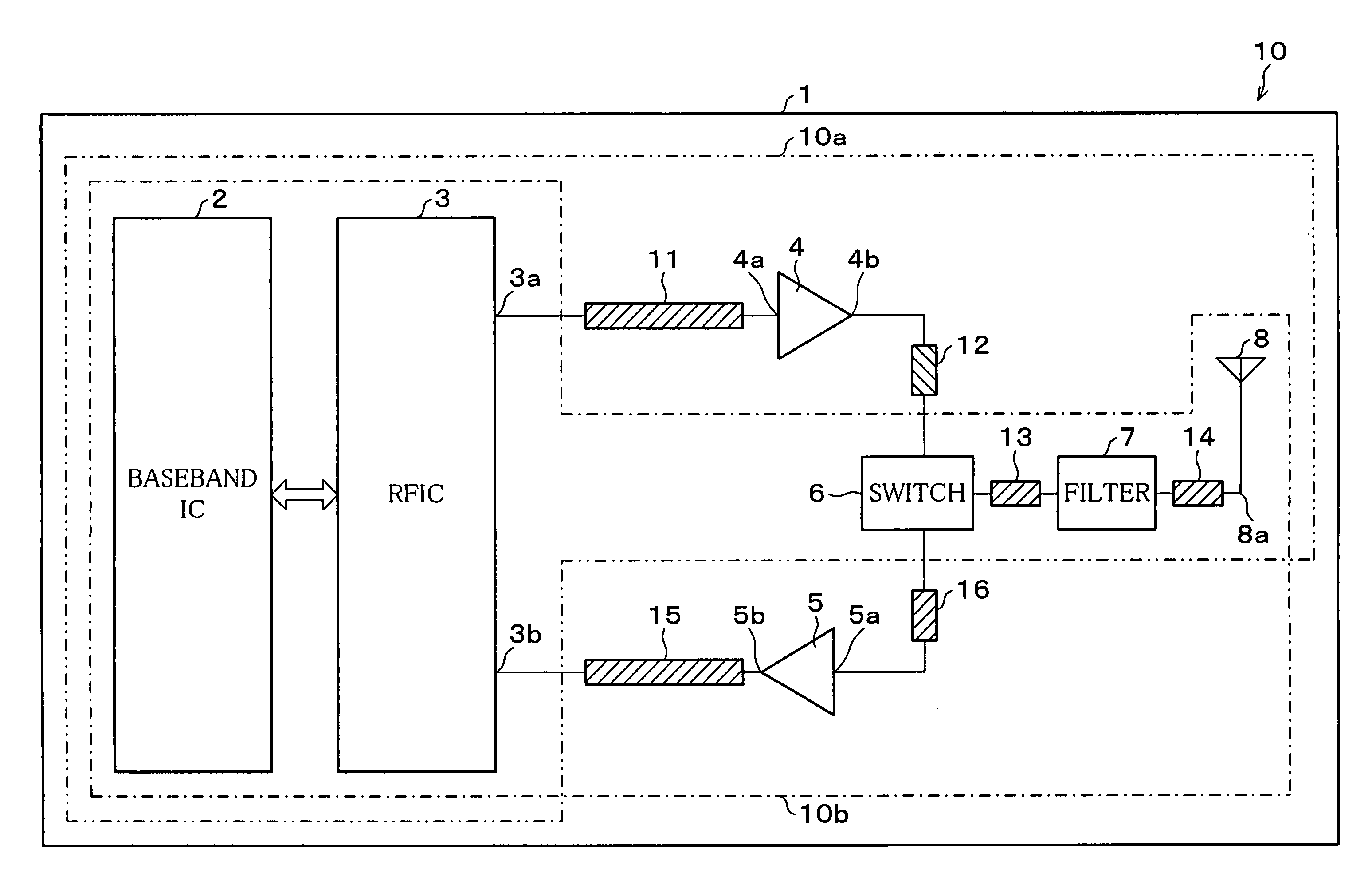
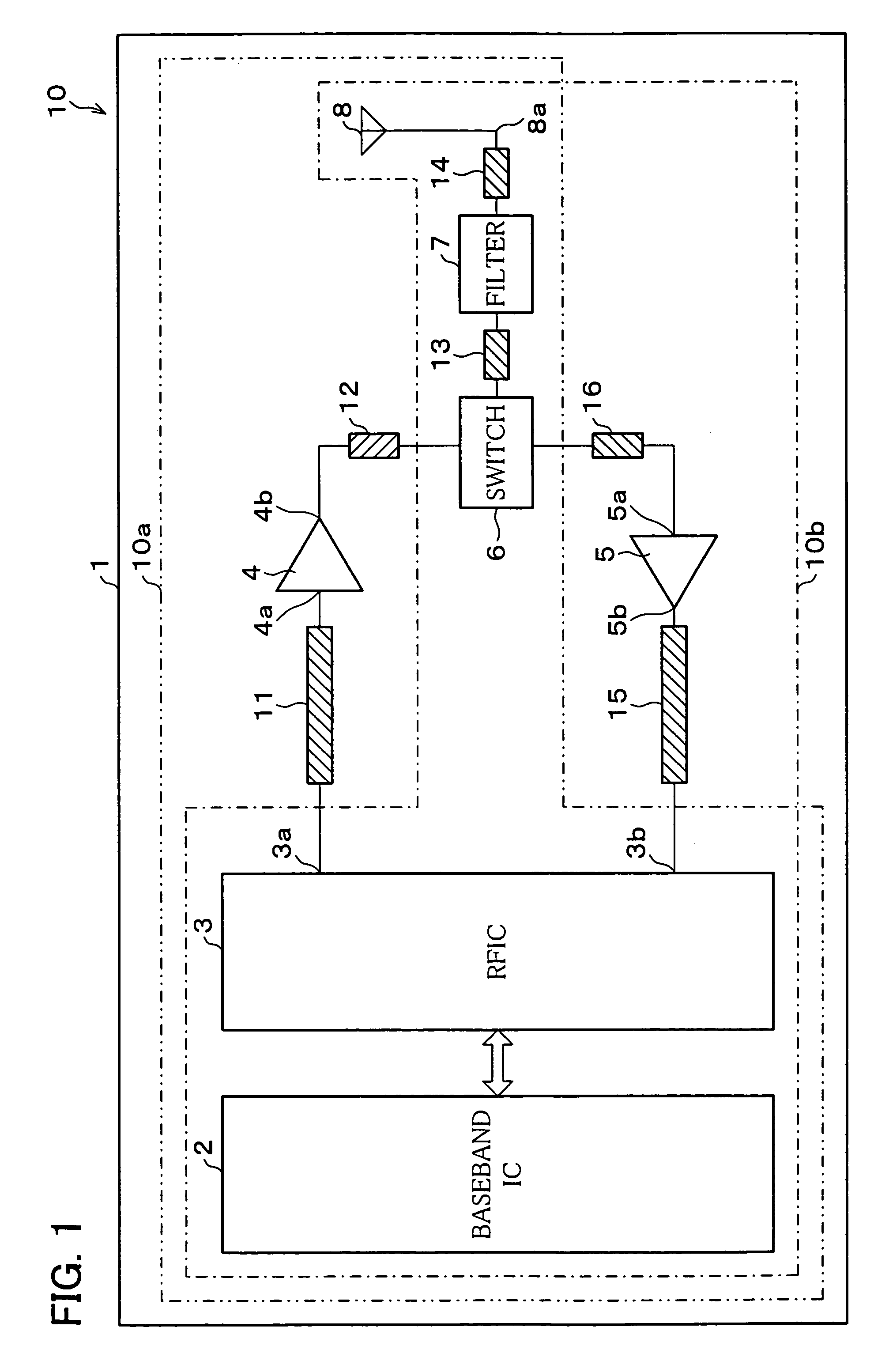
[0043]FIG. 1 illustrates a wireless LAN card 10 as a wireless communications apparatus of the present embodiment. As shown in FIG. 1, the wireless LAN card 10 includes a baseband IC 2, a RFIC 3, a transmission power amplifier 4, a low-noise amplifier 5, a transmission / reception switch 6, a band pass filter 7, and an antenna 8, which are all provided on a wireless LAN substrate 1. The a...

second embodiment

[0075]The following will explain another embodiment of the present invention with reference to FIG. 2. The structures other than those specifically explained in the present invention are identical to those described in the first embodiment. Therefore, for ease of explanation, materials having the equivalent functions as those shown in the drawings pertaining to the first embodiment above will be given the same reference symbols, and explanation thereof will be omitted here.

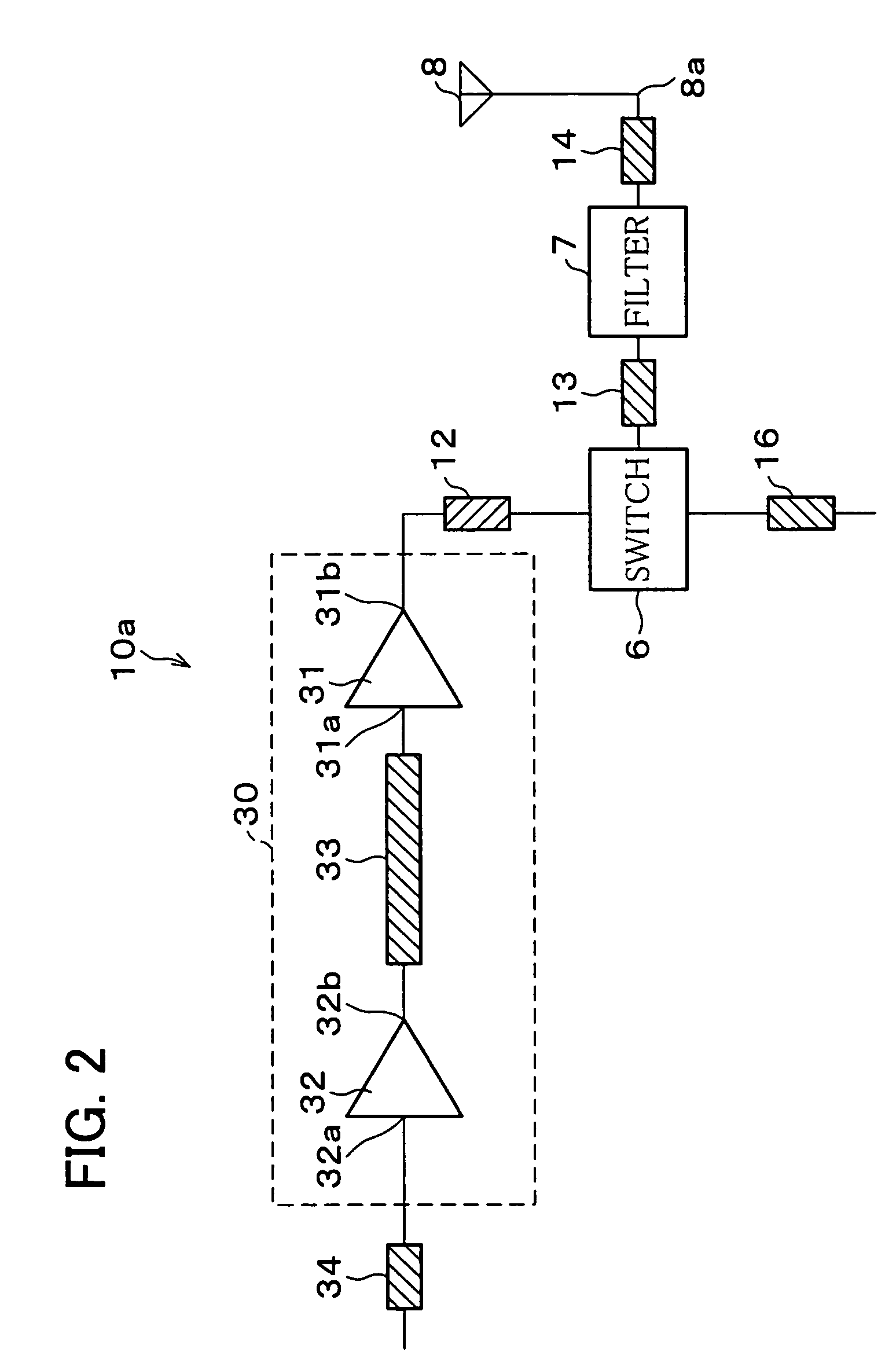
[0076]As shown in FIG. 2, the wireless LAN card 10 according to the present embodiment is different from that of the first embodiment in that the transmission power amplifier 4 is made of an active circuit block 30 that is constituted of a plurality of amplifiers, a postamplifier 31 and a preamplifier 32. Otherwise, the wireless LAN card 10 of the present embodiment is identical to that of the first embodiment.

[0077]Note that, FIG. 2 illustrates only the transmission circuit block 10a of the wireless LAN card 10. ...

third embodiment

[0085]The following will explain still another embodiment of the present invention with reference to FIG. 3. The structures other than those specifically explained in the present invention are identical to those described in the first and second embodiments. Therefore, for ease of explanation, materials having the equivalent functions as those shown in the drawings pertaining to the first and second embodiments above will be given the same reference symbols, and explanation thereof will be omitted here.

[0086]As shown in FIG. 3, the wireless LAN apparatus 50 according to the present embodiment has a different structure from that of the first embodiment. Specifically, in this embodiment, the antenna 8 and a wireless LAN main circuit body 51 are not formed on the same substrate, but a front end substrate 61 where the antenna 8 is mounted and a wireless LAN main circuit body substrate 52 are connected via a 20 cm coaxial cable 71. Further, in order to obtain a diversity effect with two ...


PUM


Abstract

A wireless communication apparatus is made up of a transmission circuit block including an antenna that is laid out such that the transmission lines, i.e., the sum of the distance connecting respective circuit blocks between an output terminal of the transmission power amplifier to an input/output terminal of the antenna is shorter than the transmission line, i.e., the sum of the distance connecting respective circuit blocks between an input terminal of a transmission power amplifier and an output terminal of a RFIC disposed at a preceding stage of the transmission power amplifier. This arrangement realizes a wireless communications apparatus ensuring improvement of overall performance of the wireless application without reducing the total transmission loss or improving the performance of individual circuits.

Description

[0001]This Nonprovisional application claims priority under 35 U.S.C. § 119(a) on Patent Application No. 2003 / 119456 filed in Japan on Apr. 24, 2003, and No. 2004 / 042054 filed in Japan on Feb. 18, 2004, and the entire contents of which are hereby incorporated by reference.FIELD OF THE INVENTION[0002]The present invention relates to a wireless communication apparatus and an information processing terminal apparatus with a wireless application, each of which includes an antenna. The present invention particularly relates to a layout of a circuit block in the wireless communication apparatus in relation to the antenna.BACKGROUND OF THE INVENTION[0003]FIGS. 5 and 6 each illustrate an example of a general arrangement of a high-frequency portion of a circuit block in a wireless communication apparatus. FIG. 5 illustrates an example of a receiver device of a TV (Television), and FIG. 6 illustrates an example of a wireless LAN (Local Area Network) card. Note that, those figures illustrate o...

Claims


Application Information

Patent Timeline
Patent Type & Authority Patents(United States)
IPC IPC(8): H01P5/12H03H7/46H04B1/38H04B1/3822H04B1/46
CPCH04B1/46
Inventor HARA, SHINJI
Owner SHARP KK
Why Eureka
Try Eureka