Friction draft gear housing having a removable end wall

a technology of friction-type draft gear and end wall, which is applied in the direction of drawing gear, printing, buffer, etc., can solve the problems of reducing the overall performance of the friction-type draft gear assembly with the integrated yoke, distributing unwanted bending stresses, and reducing the overall performance of the friction-type draft gear assembly. , to achieve the effect of reducing the overall performance of the friction-type draft gear assembly,

Inactive Publication Date: 2007-10-16
WESTINGHOUSE AIR BRAKE TECH CORP
View PDF2 Cites 2 Cited by
  • Summary
  • Abstract
  • Description
  • Claims
  • Application Information

AI Technical Summary

Benefits of technology

[0013]The present invention provides a friction draft gear assembly for railway car stock having a higher shock absorbing capacity. The friction draft gear assembly comprises a housing partially closed at a first end and open at an axially opposed second end. The first end includes a first rear portion and a smaller second rear portion outwardly extending therefrom which forms a pair of ledge members disposed intermediate the first and second rear portions for enabling the second rear portion to fit between a pair of rear stops. Utilization of the second rear portion enables the friction draft gear assembly to achieve a higher shock absorbing capacity and a longer travel in buff and draft directions. The first rear portion is adapted to receive a compressible cushioning element which extends longitudinally from the second rear portion toward the second open end. A removable end wall is attached to the second rear portion with a plurality of complimentary tapered edges for installation of the compressible cushioning element through the first end.
[0017]A further object of the present invention is to provide a friction draft gear assembly having an integrated yoke which achieves a higher shock absorbing capacity.
[0018]Yet a further object of the present invention is to provide a friction draft gear assembly having an integrated yoke which achieves a higher shock absorbing capacity and a longer travel distance.
[0019]Another object of the present invention is to provide a friction draft gear assembly having an integrated yoke which achieves a higher shock absorbing capacity and having a longer travel distance while fitting into a 24.625 inches long pocket.

Problems solved by technology

However, as it has been discovered in some applications, a major drawback of the friction-type draft gear assembly with the integrated yoke is that it will only accept a main coil spring of a smaller diameter as installation of such spring through the open yoke end is prevented by the opening in such yoke end, which is smaller than the diameter of the main coil spring.
Such arrangement enables the coupler arm to move during motion of the railway car around a curve but does not enable the coupler arm to tilt thus imparting unwanted bending stresses onto a key connection of the coupler arm with the yoke.
The bending stresses are particularly undesirable when the key is vertically disposed.
Such smaller diameter of the coil spring, as was discovered, reduces an overall performance of the friction-type draft gear assembly with the integrated yoke as compared with a similar friction-type draft gear assembly without the integrated yoke.
Attempts to compensate for such performance reduction by increasing the length of the coil spring did not achieve a desired result, as the overall performance was not sufficiently increased.

Method used


Image

  • Friction draft gear housing having a removable end wall
  • Friction draft gear housing having a removable end wall
  • Friction draft gear housing having a removable end wall

Examples


Embodiment Construction

[0031]Prior to proceeding to the more detailed description of the present invention, it should be noted that for the sake of clarity identical components, having identical functions have been identified with identical reference numerals throughout the several views, which have been illustrated in the drawing figures.

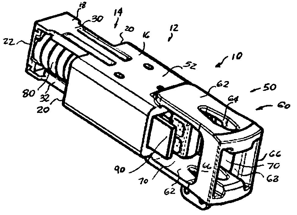
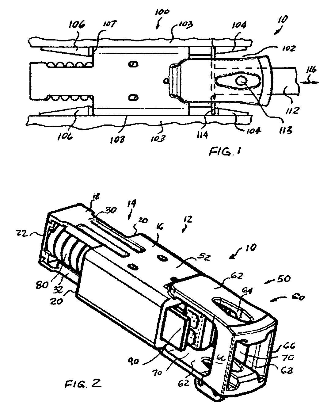
[0032]The present invention enables a friction draft gear assembly with an integrated yoke to achieve a higher shock absorbing capacity and a longer travel distance in buff and draft directions by employing a novel housing construction having a removable end wall, which enables installation of the compressible cushioning element through the first rear end.

[0033]Referring to the present invention, as shown in FIG. 1, a friction draft gear assembly, generally designated 10, is disposed within a cavity 102 of a center sill, generally designated 100, of a railway car which is not shown, but is well known in the art. A front stop 104 and an axially opposed rear stop 106 are a...


PUM


Abstract

A friction-type draft gear assembly includes a housing having an open front end and a partially closed rear end with a first and second rear portions and a pair of ledge members disposed intermediate such first and second rear portions for enabling the draft gear assembly to fit into a draft gear pocket of a predetermined length. A first rear portion is adapted to receive a compressible cushioning element with a seating arrangement abutting one end thereof which extends longitudinally from the second portion of the closed rear end toward the open front portion. A removable bottom wall is attachable either to the first or second rear portions for enabling installation of the compressible cushioning element through the first end. The open front end is adapted to receive a friction cushioning means which has a spring release mechanism for continuously urging the friction cushioning means outwardly from the compressible cushioning element thereby releasing such friction cushioning means after compression of such draft gear assembly. The open front end is configured for direct attachment to a coupler with a coupler key.

Description

CROSS-REFERENCE TO RELATED APPLICATIONS[0001]This application is closely related to U.S. patent application Ser. No. 10 / 927,911, entitled “Housing For Long Travel High Capacity Friction Draft Gear”, filed on Aug. 27, 2004, and to U.S. patent application Ser. No. 10 / 927,910, entitled “Long Travel High Capacity Friction Draft Gear Assembly”, filed on Aug. 27, 2004, and to U.S. patent application Ser. No. 10 / 928,843, entitled “Long Buff Short Draft Travel Draft Gear For Use In A 24.625 Inch Pocket”, filed on Aug. 27, 2004. These applications are assigned to the assignee of the present invention and the disclosures of these related applications are incorporated herein by reference thereto.FIELD OF THE INVENTION[0002]The present invention relates, in general, to friction-type draft gear assemblies for use in cushioning both buff and draft shocks normally encountered by railroad rolling stock during make-up and operation of a train consist on a track structure and, more particularly, this...

Claims


Application Information

Patent Timeline
Patent Type & Authority Patents(United States)
IPC IPC(8): B61G9/00
CPCB61G9/22B61G9/10B43L11/05
Inventor SOMMERFELD, HOWARDNATSCHKE, SCOTT
Owner WESTINGHOUSE AIR BRAKE TECH CORP
Why Eureka
Try Eureka