Direction indicators for vehicles

a technology for directing indicators and vehicles, applied in fixed installations, cycle equipment, lighting and heating apparatus, etc., can solve the problems of difficult to increase the efficiency of reflecting and collecting rays of light emitted from lamps, and achieve the effect of ensuring brightness and visibility

Active Publication Date: 2007-10-16
KAWASAKI MOTORS LTD
View PDF7 Cites 7 Cited by
  • Summary
  • Abstract
  • Description
  • Claims
  • Application Information

AI Technical Summary

Benefits of technology

[0007]In view of the foregoing problems and inconveniences inherent in the conventional direction indicator discussed above, the present invention is intended to provide an improved direction indicator of a compact design effective to secure brightness and visibility during the blinking operation of the direction indicator.
[0010]In a preferred embodiment of the present invention, the light emitter may have a light emitting portion positioned within an inner space of the lens member. The inner space of the lens member referred to above is defined in the lens member and delimited by an inner surface of the lens member and the imaginary plane passing in touch with a peripheral edge which defines a joint edge of the lens member engageable with the indicator body. This disposition of the light emitter is particularly advantageous in that since a light emitting portion of the light emitter can be positioned within a space defined on one side adjacent the lens member, rather than the plane of joint between the indicator body and the lens member, the light emitter can be visible directly from top and bottom. Therefore, rays of light emanating from the light emitter can be projected upwardly and downwardly without being disturbed by the indicator body. In particular, upward illumination allows a truck driver, seated in a cabin seat positioned relatively high above the road surface, to look at the direction indicator.
[0011]In another preferred embodiment of the present invention, the reflector may extend from one end of the plane of joint between the indicator body and the lens member to a portion adjacent the laterally outer vertex portion of the lens member, which outer vertex portion is positioned adjacent the other end of such joint edges. According to this structural feature, by allowing the reflector to extend to the position adjacent the laterally outer vertex portion of the lens member as described above, the reflector can have an increased size. This leads to increase of the area of the reflecting surface of the reflector as compared with that in the conventional direction indicator, with the consequence that the efficiency of collecting rays of light from the light emitter can be increased to increase the illuminance.
[0012]In a further preferred embodiment of the present invention, the light emitter may be a lamp bulb including a light emitting portion having a filament built therein, in which case the lamp bulb may be supported by the indicator body with a longitudinal axis of the lamp bulb inclined relative to a longitudinal direction of the vehicle body structure. According to this structural feature, when the lamp bulb generally having a substantial length in a direction along the longitudinal axis thereof is supported by the indicator body with the longitudinal axis thereof inclined relative to the longitudinal direction of the vehicle body, the length of the lamp as measured in a direction conforming to the longitudinal sense of the vehicle body structure can be reduced, allowing the direction indicator as a whole to have a reduced size in a direction conforming to the longitudinal sense of the vehicle body. Accordingly, as compared with the conventional direction indicator, the direction indicator of the present invention can be manufactured compact in size and lightweight.
[0014]The reflector may be bonded to the lens member, so that, during the repair and / or servicing of the light emitter, the assembly of the reflector integrated together with the lens member can be removed from the indicator body to thereby facilitate the repair and / or servicing work.

Problems solved by technology

In other words, the space where the reflector 24 can be placed is limited and, therefore, the width L of the reflecting surface 24a of the reflector 24 as measured in a direction substantially perpendicular to the longitudinal sense of the vehicle body structure cannot be increased, resulting in difficulty in increasing the efficiency of reflecting and collecting rays of light emitted from the lamp 25.

Method used


Image

  • Direction indicators for vehicles
  • Direction indicators for vehicles
  • Direction indicators for vehicles

Examples


Embodiment Construction

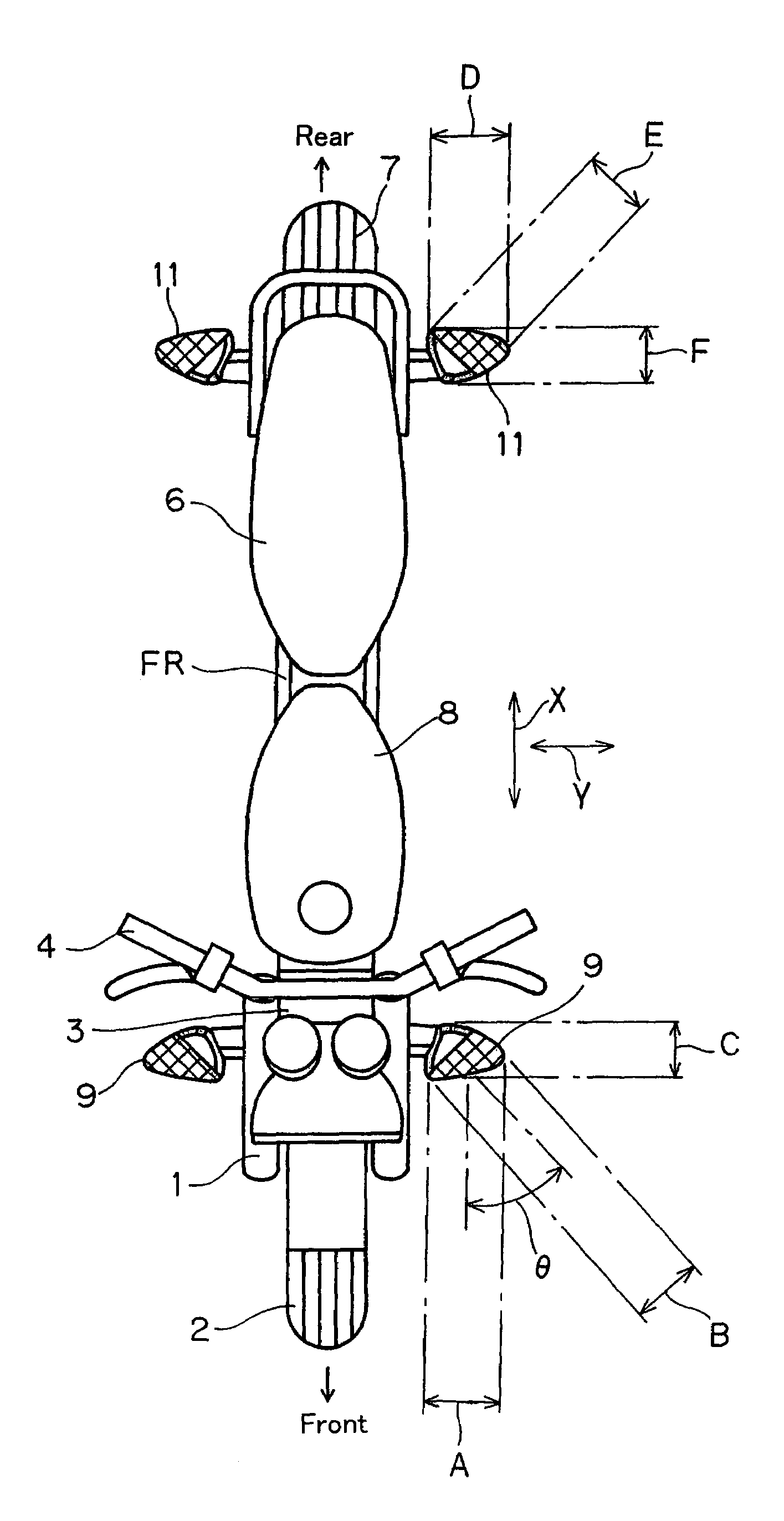
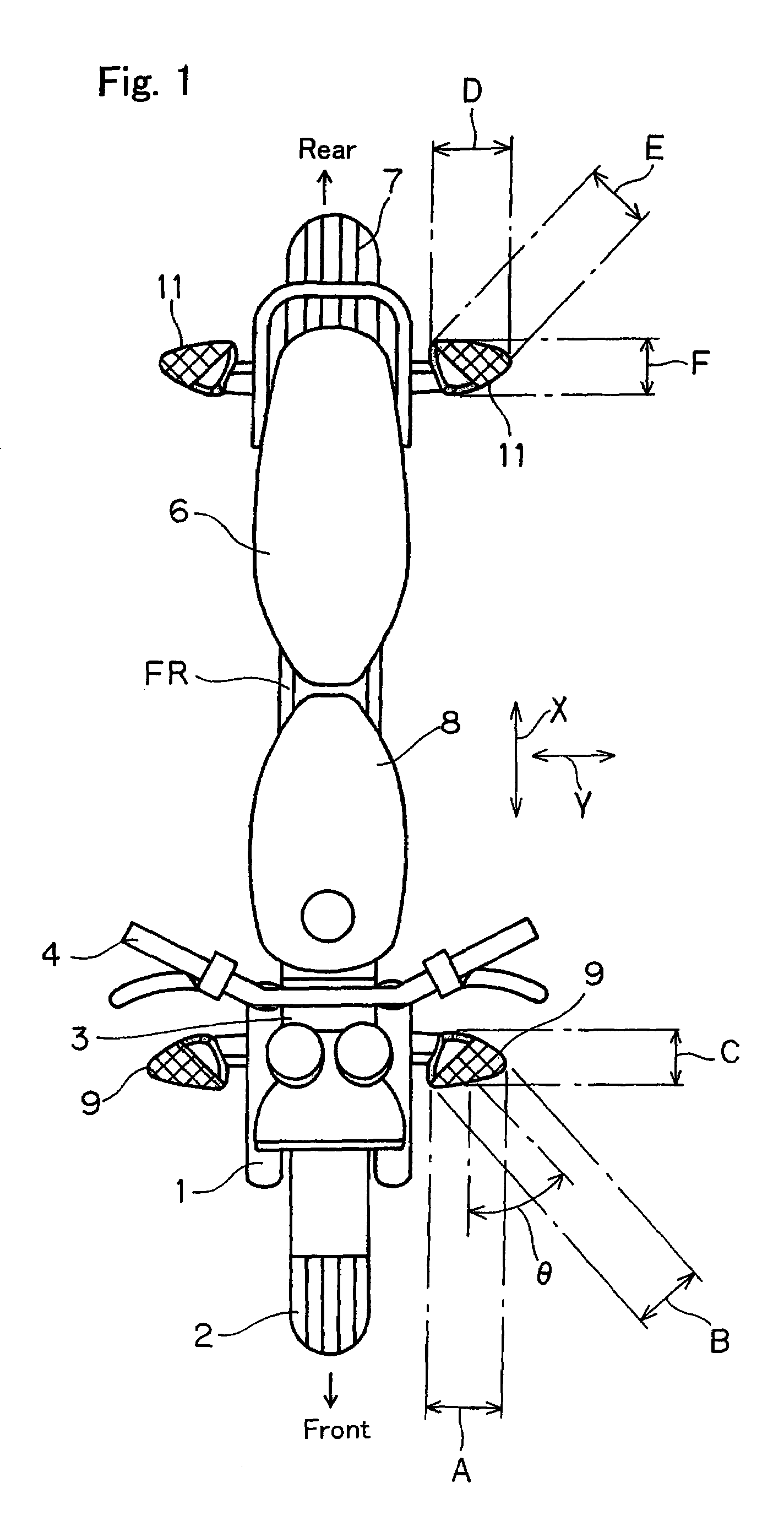
[0024]Hereinafter, a preferred embodiment of the present invention will be described with reference to the accompanying drawings, particularly to FIGS. 1 to 5. FIG. 1 illustrates, in a schematic top plan representation, an automotive vehicle, for example, a motorcycle equipped with front and rear pairs of left and right direction indicators designed according to the preferred embodiment of the present invention. Specifically, the motorcycle shown therein includes a motorcycle frame structure FR connected at a front end thereof with a front fork 1 with a front wheel 2 rotatably carried at a lower end thereof. A handlebar 4 is mounted on an upper bracket 3 that is rigidly connected with an upper end of the front fork 1, and a seat assembly 6 is mounted on a rear end portion of the motorcycle frame structure FR. A rear drive wheel 7 is rotatably supported by a swingarm (not shown) pivotally connected with a portion of the motorcycle frame structure FR at a location rearwardly downwardl...


PUM


Abstract

To provide a direction indicator of a compact design effective to secure brightness and visibility during the blinking operation of the direction indicator, the direction indicator (9 or 11) includes an indicator body (92) adapted to be mounted on a vehicle body structure (FR), a lens member (93) mounted on the indicator body (92), a light emitter (12) and a reflector (13) positioned inwardly of the lens member (93), the reflector (13) reflecting an illuminating light, emitted from the light emitter (12), towards an intended area. A plane of joint (92b, 93b) between the indicator body (92) and the lens member (93) is inclined relative to a widthwise direction of the vehicle body structure (FR), and the lens member (93) has a laterally outer vertex portion (93a) protruding laterally outwardly from a position of a laterally outer vertex portion (92a) of the indicator body (92).

Description

BACKGROUND OF THE INVENTION[0001]1. Field of the Invention[0002]The present invention generally relates to a direction indicator (a turn signal lamp) for vehicles and, more particularly, to a compact direction indicator of a type effective to secure brightness and visibility during the blinking operation of the direction indicator.[0003]2. Description of the Prior Art[0004]In general, the conventional direction indicator used in vehicles, particularly in motorcycles includes, as shown in a schematic plan view of the front direction indicator in FIG. 6, a generally cup-shaped indicator body 20 opening forwardly of the vehicle and having a support arm 20a supported by the vehicle body structure, and a lens member 21 mounted on the indicator body 20 so as to cover the front opening of the indicator body 20. Within the interior of the direction indicator delimited between the indicator body 20 and the lens member 21, a reflector 24 is disposed as shown in FIG. 7, having a reflecting sur...

Claims


Application Information

Patent Timeline
Patent Type & Authority Patents(United States)
IPC IPC(8): B60Q1/26B60Q1/34B62J6/00F21S8/10F21W101/12F21Y101/00G01B3/20
CPCB62J6/005B60Q1/34B62J6/055
Inventor KOUCHI, KAORUKANOU, MOTOAKI
Owner KAWASAKI MOTORS LTD
Why Eureka
Try Eureka