Circuit breaker

a circuit breaker and circuit technology, applied in the field of circuit breaker, can solve the problems of conventional circuit breaker, product damage, heat dissipation of metal strips,

Active Publication Date: 2007-10-16
HUANG ALBERT
View PDF39 Cites 13 Cited by
  • Summary
  • Abstract
  • Description
  • Claims
  • Application Information

AI Technical Summary

Problems solved by technology

When an electrical current is excessively high and generates dangerous heat, the bimetal strip becomes heated and distorts, whereby a tip of the bimetal strip separates from the second conducting strip.
If the friction from the button is too big for the bimetal strip to act quickly, a product may be damaged because of the heavy current not being timely interrupted.
However, disadvantages of the conventional circuit breaker are described as follows:

Method used


Image

  • Circuit breaker
  • Circuit breaker
  • Circuit breaker

Examples


Embodiment Construction

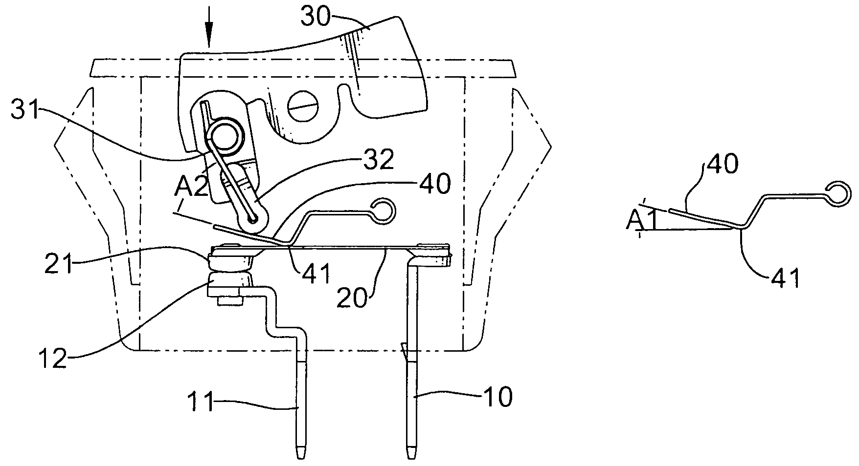
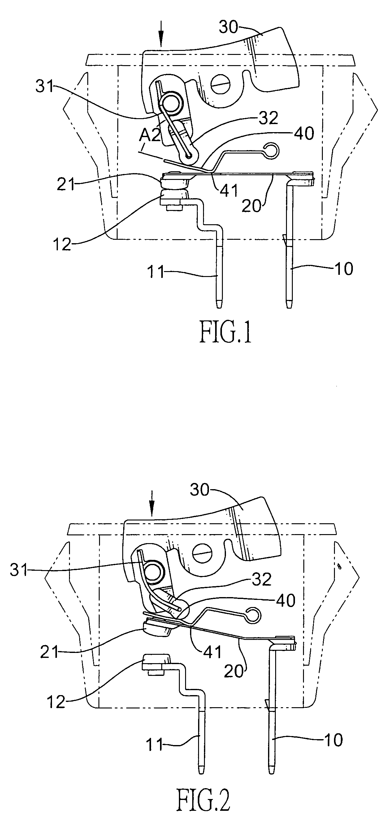
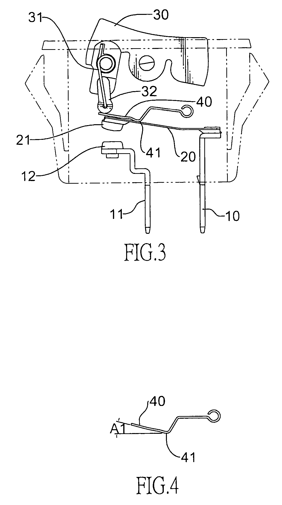
[0024]With reference to FIG. 1, a circuit breaker comprises a shell, and a first conducting strip (10) and a second conducting strip (11) respectively provided on a lower end of the shell. A first terminal (12) is mounted on an upper end of the second conducting strip (11) and a bimetal strip (20) is horizontally and securely mounted on an upper end of the first conducting strip (10) wherein a first tip of the bimetal strip (20) is connected to the first conducting strip (10) and a second terminal (21) securely connects to a second tip of the bimetal strip (20) and is detachably in contact with the first terminal (12).

[0025]A button (30) is pivotally mounted on an upper end of the shell, a curved spring (31) is mounted on a lower end of the button (30) and a finger (32) is provided on a lower end of the curved spring (31). A lever (40), which has a smooth surface, is mounted between the finger (32) and the bimetal strip (20). The lever (40) is bent to form a pivot point (41), which ...


PUM


Abstract

A breaker has a first conducting strip and a second conducting strip respectively mounted on a lower end of a shell; a first terminal mounted on the second conducting strip; a bimetal strip securely provided on a first conducting strip; a second terminal mounted on a tip of the bimetal strip and detachably connected to the first terminal; a button provided on an upper end of the shell; a finger pivotally provided under the curved spring; and a lever with a smooth surface provided between the bimetal strip and the finger wherein an end of the lever is bent to form an angle. Hence, the finger can slide on the smooth surface of the lever so that the button can completely return to an original status. Furthermore, when the angle is small, the finger counter clockwise rotates with a small stored power of the bimetal strip.

Description

BACKGROUND OF THE INVENTION[0001]1. Field of the Invention[0002]The present invention relates to a circuit breaker, and more particularly to a circuit breaker which can interrupt an excessively high electrical current consumption.[0003]2. Description of Related Art[0004]A circuit breaker is provided in a distribution box to prevent a high electrical current consumption from causing an accident. The circuit breaker is composed of a shell, a first and a second conducting strip provided in the shell, and a bimetal strip securely mounted on an upper end of the first conducting strip. The bimetal strip, i.e., two metal flats which have different thermal expansion factors, can electrically connect to the second conducting strip.[0005]When an electrical current is excessively high and generates dangerous heat, the bimetal strip becomes heated and distorts, whereby a tip of the bimetal strip separates from the second conducting strip. Hence, the electrical current circuit is interrupted to ...

Claims


Application Information

Patent Timeline
Patent Type & Authority Patents(United States)
IPC IPC(8): H01H37/70H01H37/52
CPCH01H73/26
Inventor HUANG, ALBERT
Owner HUANG ALBERT
Why Eureka
Try Eureka