System and method for power load management

a technology of power load management and power supply, applied in the integration of power network operation systems, ac network voltage adjustment, sustainable buildings, etc., can solve the problems of tripping of over-current protection for alternate power sources, expensive and impractical solutions

Inactive Publication Date: 2007-09-27
DYNAGEN TECH
View PDF12 Cites 110 Cited by
  • Summary
  • Abstract
  • Description
  • Claims
  • Application Information

AI Technical Summary

Benefits of technology

[0009] It is an object of the present invention to obviate or mitigate at least one disadvantage of previous load management systems.

Problems solved by technology

A typical problem with automatic transfer switches installed prior to the use's service installation is the matching of the load power draw with the available power supplied by an alternate power supply, such as on-site generator (gas or diesel engine-generator).
If any load in the facility is capable of drawing power from the alternate power source, then concerns are raised over possible overloading of the alternate power source capacity leading to the tripping of over-current protection for the alternate power source.
However, this is a very expensive and impractical solution.

Method used


Image

  • System and method for power load management
  • System and method for power load management
  • System and method for power load management

Examples


Embodiment Construction

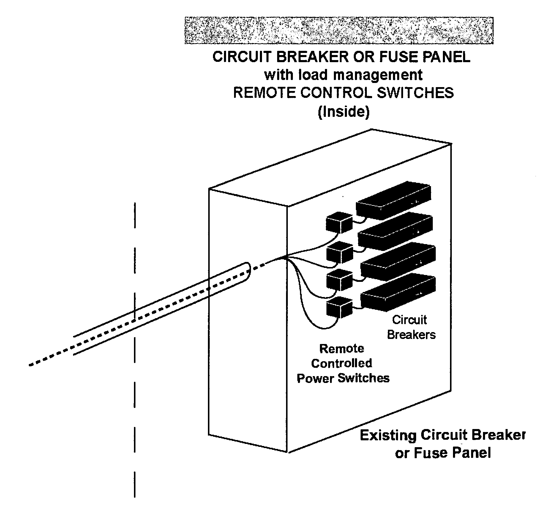
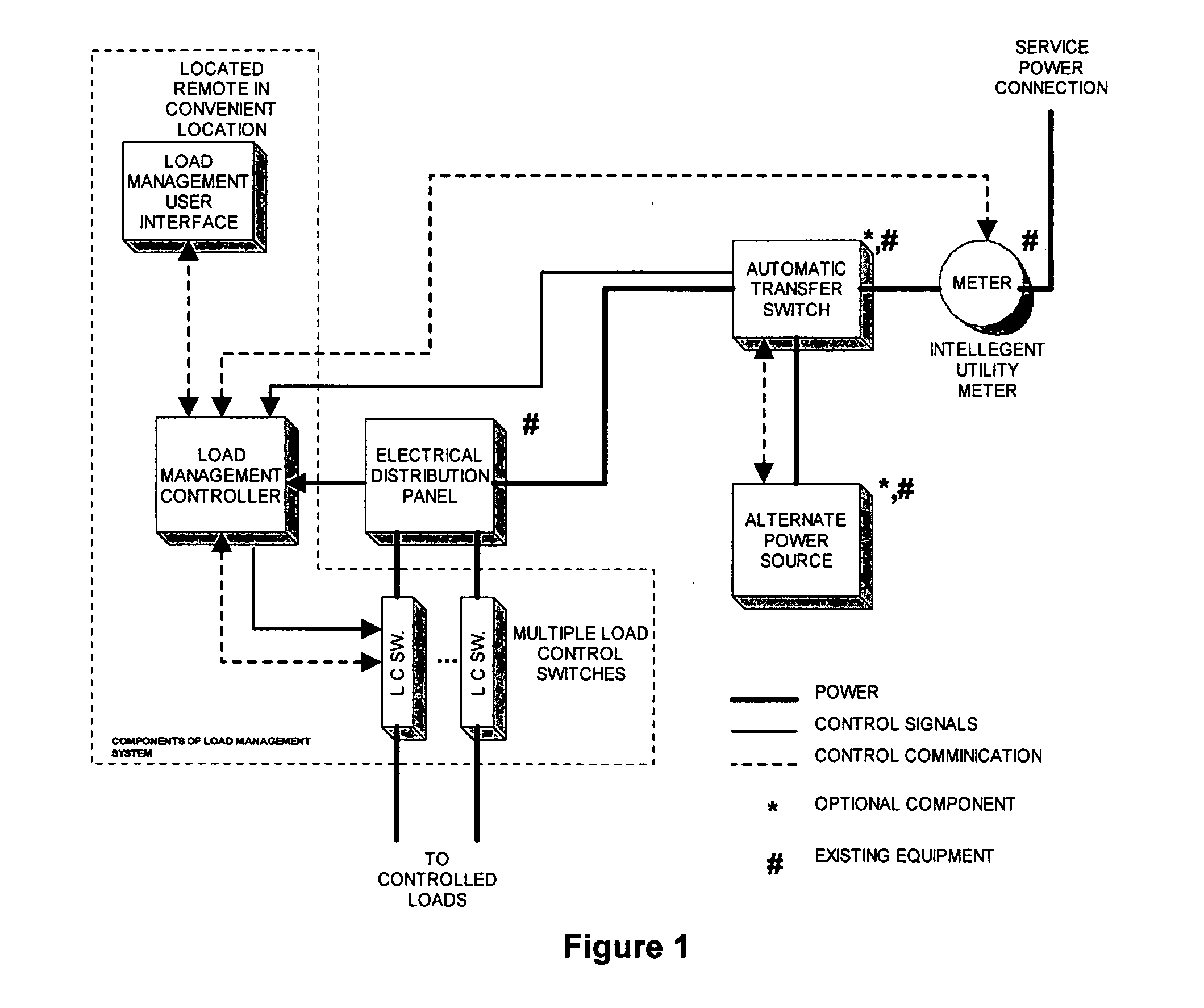
[0027] Generally, the present invention provides a power load management system for regulating power demand on the distribution panel of a residence or building. Load control switches placed in-line between circuit breakers of the distribution panel and loads associated with those circuit breakers and provide load feedback data to a load management controller. The load management controller monitors the load feedback data and other operational parameters for selectively switching load control switches to the open or closed circuit states to regulate the total load demanded within the set limits of the power source. The load management controller includes adaptive algorithms to automatically prioritize loads based on user and utility applied weighting factors, and patterns of loading based on accumulated data related to time and date.

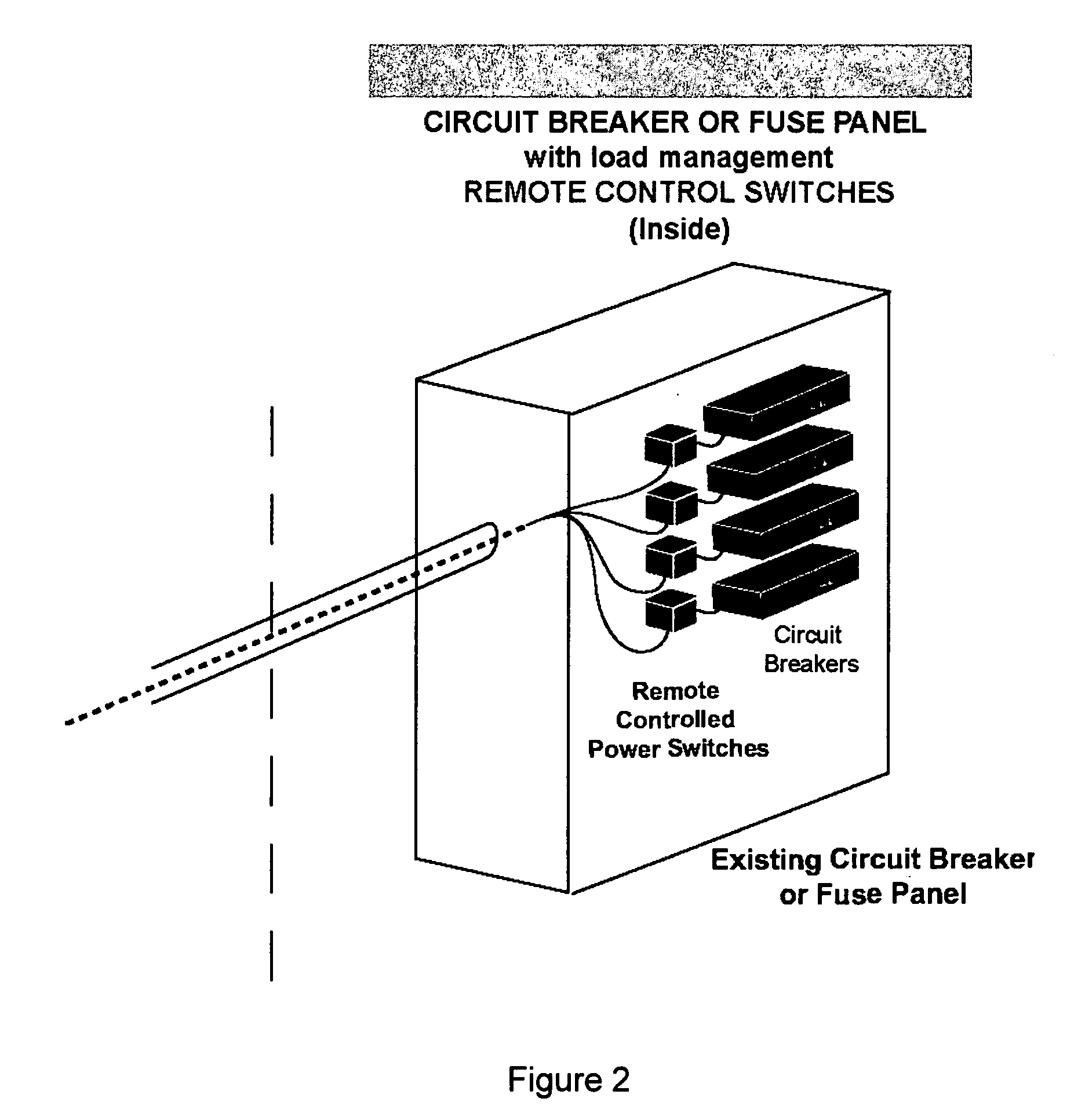
[0028] Load management according to the embodiment of the present invention are achieved in part through the application of miniaturized, electrically ...


PUM


Abstract

A power load management system for regulating power demand from a distribution panel of a residence or building is disclosed. Load control switches placed in-line between circuit breakers of the distribution panel and the loads they control, such as a water heater, pump, AC unit etc., provide load feedback data to a load management CPU. The load management CPU monitors the load feedback data and other operational parameters for selectively switching load control switches to the open circuit state to ensure that the total load demanded does not exceed the demand limits imposed by the power source. The load management CPU includes adaptive algorithms to automatically prioritize loads based on user and utility applied weighting factors, and patterns of loading based on time and date.

Description

CROSS-REFERENCE TO RELATED APPLICATIONS [0001] This application is a Continuation in Part application of U.S. patent application Ser. No. 10 / 654,440 filed Sep. 4, 2003. [0002] U.S. patent application Ser. No. 10 / 654,440 claims priority from U.S. Provisional Patent Application Ser. No. 60 / 407,949 filed Sep. 5, 2002.FIELD OF THE INVENTION [0003] The present invention relates generally to power load management systems. More particularly, the present invention relates to managing loads for alternate power supplies and during conditions of limited supply imposed by energy provider. BACKGROUND OF THE INVENTION [0004] A typical problem with automatic transfer switches installed prior to the use's service installation is the matching of the load power draw with the available power supplied by an alternate power supply, such as on-site generator (gas or diesel engine-generator). An example of an automatic transfer switch installed upon a service installation is shown in FIG. 11. [0005] In FI...

Claims


Application Information

Patent Timeline
Patent Type & Authority Applications(United States)
IPC IPC(8): H02J3/14H02J9/06H02J13/00
CPCH02J3/14Y04S40/126H02J13/002H02J13/0062H02J13/0075H02J2003/143Y02B70/3225Y02B70/3266Y02B70/3291Y02B90/222Y02B90/2615Y02B90/2638Y02B90/2653Y04S20/12Y04S20/222Y04S20/242Y04S20/248Y04S40/121Y04S40/124H02J9/062H02J2310/14H02J13/00007H02J13/00016H02J13/00004Y02B70/30Y02B90/20H02J13/00022
Inventor WAREHAM, PAULMACNEIL, STEPHENMACLEAN, MICHAELSAMSON, SHANE
Owner DYNAGEN TECH
Why Eureka
Try Eureka