Hook latch

a latch and hook technology, applied in the field of latches, can solve the problems of long lock cylinders and locked areas

Active Publication Date: 2007-10-30
SOUTHCO
View PDF12 Cites 0 Cited by
  • Summary
  • Abstract
  • Description
  • Claims
  • Application Information

AI Technical Summary

Benefits of technology

[0011]It is an object to provide an improved lock cylinder having master key capability which is readily adaptable to different thicknesses of doors or closure members.
[0012]Another object of the present invention is to provide a door lock that is easy to operate.
[0013]A further object of the invention is to provide a lock cylinder which has a very low profile or thickness and which can be used in applications where space and thickness is a limiting factor.
[0016]A further object of this invention is to provide such a lock cylinder with structural components which offers ease of assembly, and reliable operations.
[0018]When the rotation of the knob about a first axis or key about a second axis causes the shaped protuberances on the locking ring and the rotation means to extend closest to the opposing axis, the engagement of the protuberances on the locking plate extend the locking plate into an extended position against the urging of a biasing means or coil spring mounted on a biasing means support on the locking plate. As the rotation means is rotated a prong on the actuator plate rides over a detent on the locking plate to a position where the locking plate and actuator plate are in the latched position wherein the locking plate detent prevents motion of the actuator plate back to the open position. The actuator plate is prevented from moving to the open position by interference of the actuator plate prong with the detent on the locking plate until the detent is withdrawn by the withdrawal of the locking plate detent upon rotation of the rotation means or key by a user. Accordingly, accidental motion of the first pawl or second pawl in the latched position or unauthorized tampering with the first or second pawl would not result in the hook latch being opened due to the interference of the actuator plate prong with the detent of the locking plate.
[0019]The objects of the present invention are also realized in a lock cylinder configured for a key. Master key functionality is attained by adding an annular ring to the basic lock cylinder structure and modifying the profile of the low level security key. A separate key profile for each key is provided to provide the master key capability. A portion of one of the bits of the master key is machined deeper than the low level security key and has a key stop where the bit abuts the stem. When the lock cylinder is provided with a master annular ring, the lock cylinder can only be operated by the master key and not the limited access low level security key due to the presence of a tab on the master annular ring provided on the front of the lock cylinder which prevents entry of the limited access or low level security key into the lock cylinder. The master key can also operate the lock cylinder when the lock cylinder is fitted with a low level security annular ring which does not have the tab which is present on the master annular ring.

Problems solved by technology

In addition, it is oftentimes desired that the lock cylinder of latches generally have the capability of being opened with a master key in addition to a lower level security key.
However, there may be locked areas which are only to be accessible by the captain of the ship.
This resulted in very long lock cylinders which oftentimes would protrude from the back side of the door or panel due to the length of the lock cylinders.

Method used


Image

  • Hook latch
  • Hook latch
  • Hook latch

Examples


Embodiment Construction

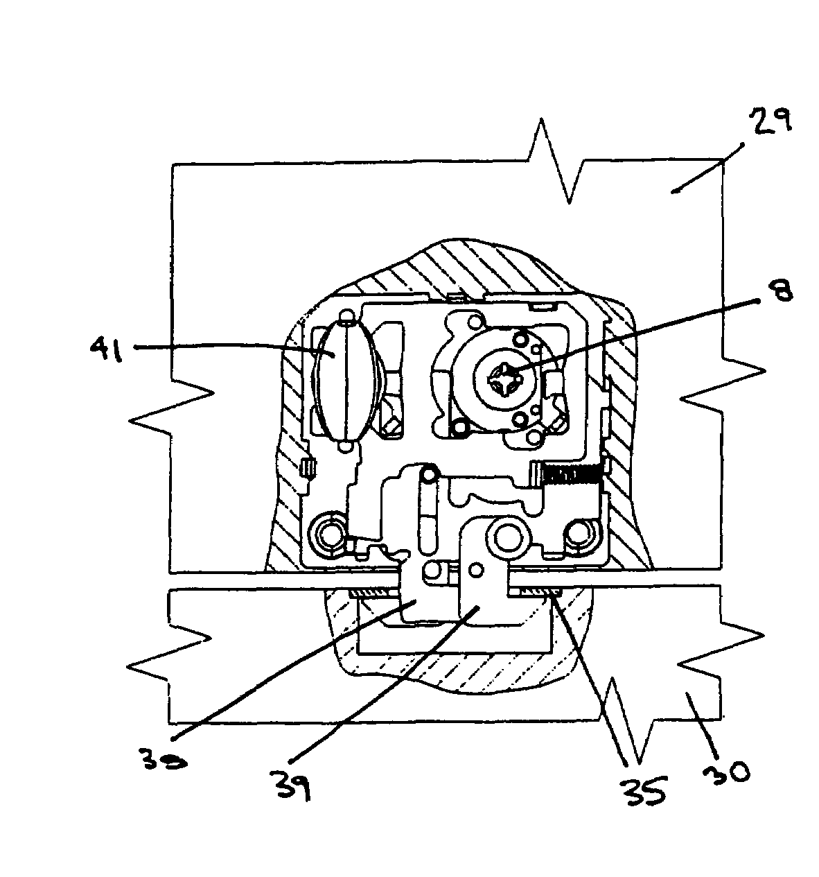
[0053]FIGS. 16-19 show the hook latch of the present invention in a clamshell configuration in a door 29. Rotation of the key 1 or knob 41 actuates the latch and first and second pawl move from the latched and unlatched position. FIG. 20 shows the knob stem 48 which actuates rotation means 33 which in turn actuates rotation means protuberance 34 seen in FIG. 22 where the hook latch latches door 29 to frame 30.

[0054]In FIG. 22, rotation of the low level security annular ring 7 by a key (not shown) rotates actuator 28 such that locking ring protuberance 31 of locking ring 32 has displaced actuator plate 37, by engagement of the locking ring protuberance 31 with second actuator plate aperture 51, into the extended position in which first pawl 38 and second pawl 39 are latched.

[0055]In the exploded views of FIGS. 23 and 24 of the hook latch, it can be seen that the rotation of a knob which in turn rotates rotator 49 in yoke 55 causes rotation means protuberance 34 in first actuator plat...


PUM


Abstract

A hook latch for fastening and unfastening a closure member to a keeper in a latched position. The hook latch is moveable between the latched position and an open position. The hook latch comprises a rotation means which preferably comprises a knob connected to a cam shaped protuberance which acts upon an actuator plate and a locking plate. Upon rotation of either the knob or the key which is inserted in a lock cylinder which has a locking ring having a cam-shaped protuberance, the cam-shaped protuberances displace both the actuator plate and the locking plate.

Description

[0001]This application claims the benefit of U.S. Provisional Application No. 60 / 562,842 filed Apr. 16, 2004 entitled “Hook Latch” the entire specification of which is incorporated by reference.BACKGROUND OF THE INVENTION[0002]The present invention relates generally to latches.[0003]Latches are known in the art and are provided for the latching and the opening of a member such as a door or panel.[0004]In addition, it is oftentimes desired that the lock cylinder of latches generally have the capability of being opened with a master key in addition to a lower level security key. This is particularly true in the case of marine applications where the individual members of a crew need access to individualized areas which the captain of the vessel also needs access to. However, there may be locked areas which are only to be accessible by the captain of the ship. In such cases, the captain would need a high level security key or master key to access his areas and also the crews areas.[0005...

Claims


Application Information

Patent Timeline
Patent Type & Authority Patents(United States)
IPC IPC(8): E05B65/06E05B19/00E05B27/00E05B35/10E05B63/00E05B63/14E05B63/18
CPCE05B27/0053E05B63/0013E05B35/10E05B19/0047E05B63/18E05B63/14Y10T70/5354Y10T292/0831Y10T292/0852Y10T292/0913E05B63/00E05B65/06
Inventor JOHANSSON, HENRICJOHANSSON, TORSTENMAGNUSSON, CLAES
Owner SOUTHCO
Why Eureka
Try Eureka