
Tilt and lift device for adjusting tilt angle and height of slats of a Venetian blind

a technology of tilt and lift device and venetian blind, which is applied in the direction of door/window protective device, construction, building components, etc., can solve the problems of only being used with venetian blinds lighter than alight, the tilt and lift device cannot be effectively adjusted, and the venetian blind cannot be smoothly moved

Inactive Publication Date: 2007-10-30
LIN GWO TSAIR
View PDF8 Cites 49 Cited by
  • Summary
  • Abstract
  • Description
  • Claims
  • Application Information

AI Technical Summary

Benefits of technology

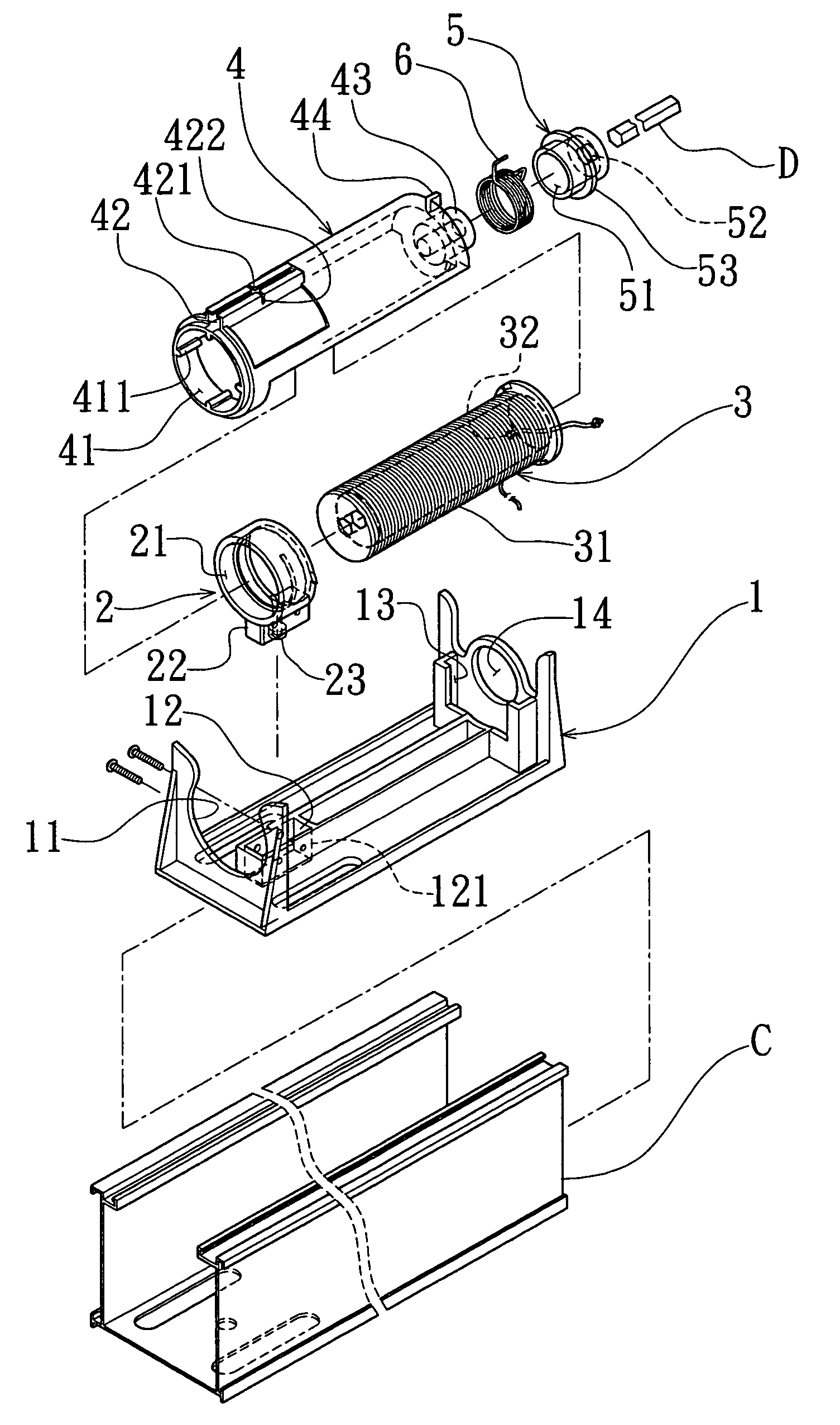
"The present invention provides an improvement on a tilt and lift device of a Venetian blind to overcome the problem of excessive tilting during operation. The device includes a manual control, a supporting base, a square transmission shaft, a rotary ring, a torsion spring, a reel tube, and an external tube. The external tube is angularly displaceable about the axis, and has several bar-shaped protrusions on an inner side, and a protrusion held between the two ends of the torsion spring. A tilt cord is passed over and joined to the external tube. The external tube will be stopped from turning beyond a certain position by the supporting base. The reel tube is passed into the external tube, with the bar-shaped protrusions of the external tube helping the reel tube keep balance, and has a square axial hole, and continuous spiral groove, on which a lift cord is wound along. The reel tube engages an internal thread of a support ring at the spiral groove so as to be linearly displaceable when turning. The transmission shaft is passed through the external tube, and the square holes of the reel tube and the rotary ring. One of two ends of the torsion spring will be pressed against the protrusion of the external tube when the transmission shaft is turned. Thus, when the manual control is operated, the torsion spring will be slightly enlarged, and loosen its grip on the rotary ring after the external tube is stopped at said certain position by the supporting base, allowing the rotary ring, the transmission shaft, and the reel tube to be turned together."

Problems solved by technology

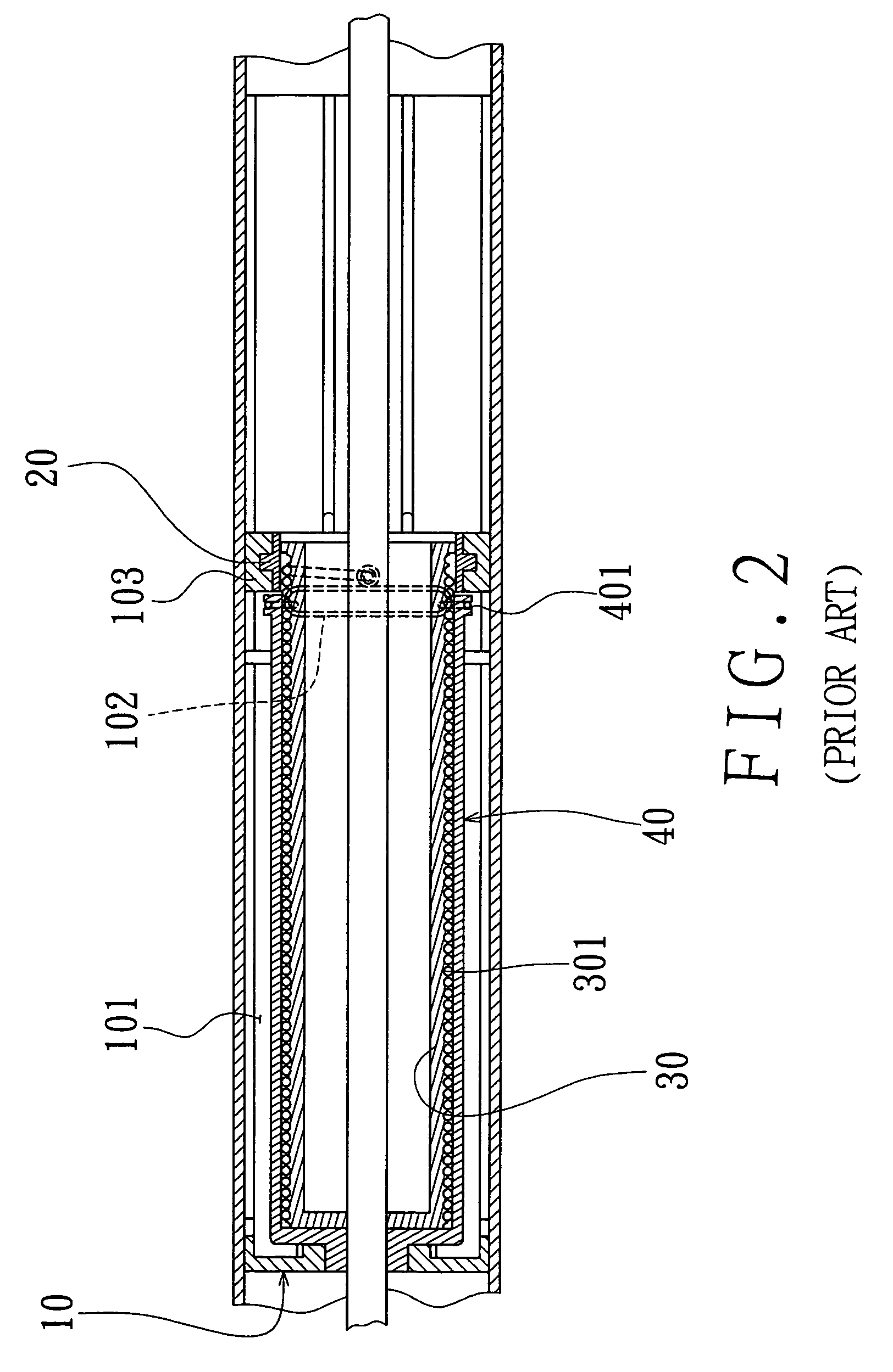
The device can only be used with a certain thickness of lift cord and tilt cord, as shown in FIG. 3; if the original lift cord is replaced with one with excessive thickness, the new one will be jammed between the external tube and the reel tube, as shown in FIG. 4, and the Venetian blind can't be smoothly moved; if the original tilt cord is replaced with a thicker one or a thinner one, there won't be enough friction between the new tilt cord and the external tube, as shown in FIG. 4, and the tilt angle of the slats can't be effectively adjusted.
Consequently, the tilt and lift device can only be used with Venetian blinds lighter than a certain weight, and it can't be used with large and heavy Venetian blinds because the original lift cord and the original tilt cord thereof aren't strong enough.
However, the second conventional device has a more complicated structure and higher manufacturing cost than the first one, and it takes more time and labor to assemble the second device.
Therefore, the second conventional tilt and lift device isn't economical to use.

Method used


Image

  • Tilt and lift device for adjusting tilt angle and height of slats of a Venetian blind
  • Tilt and lift device for adjusting tilt angle and height of slats of a Venetian blind
  • Tilt and lift device for adjusting tilt angle and height of slats of a Venetian blind

Examples


Embodiment Construction

[0025]Referring to FIGS. 6 and 8, a preferred embodiment of a tilt and lift device of a Venetian blind includes a manual control member (not shown), a supporting base 1, a support ring 2, a reel tube 3, an external tube 4, a rotary ring 5, and a square transmission shaft (D).

[0026]The manual control member is secured on an uppermost part of a door (window), and connected to one end of the transmission shaft (D) such that the transmission shaft (D) can be turned in a desired direction by means of operating the manual control member.

[0027]The supporting base 1 is securely held in a horizontal elongate beam (C) secured on an upper part of the door (window), and it has a concave locating portion 11 at one end, a fitting gap 12, a locating portion 14 at the other end, and a receiving space 13 next to the locating portion 14.

[0028]The support ring 2 has a hole 21, an internal thread, a fitting protrusion 22, and a through hole 23 on the fitting protrusion 22. The support ring 2 is passed ...


PUM


Abstract

A Venetian blind includes a control, a square transmission shaft joined to the control, an external tube, and a reel tube having an external spiral groove, along which a lift cord is wound; the external tube has two elongate protrusions parallel to an axis thereof on an outer side; the elongate protrusions define a tunnel in between, and have opposing gaps on the edges thereof, and they are formed with such a shape that a lengthways-extending aperture is provided between edges thereof; a tilt cord is passed over, and joined to the external tube with a middle knot thereof being detained in the tunnel of the external tube, and with two ends thereof being passed through the gaps of the elongate protrusions of the external tube; thus, the tilt cord will always move together with the external tube.

Description

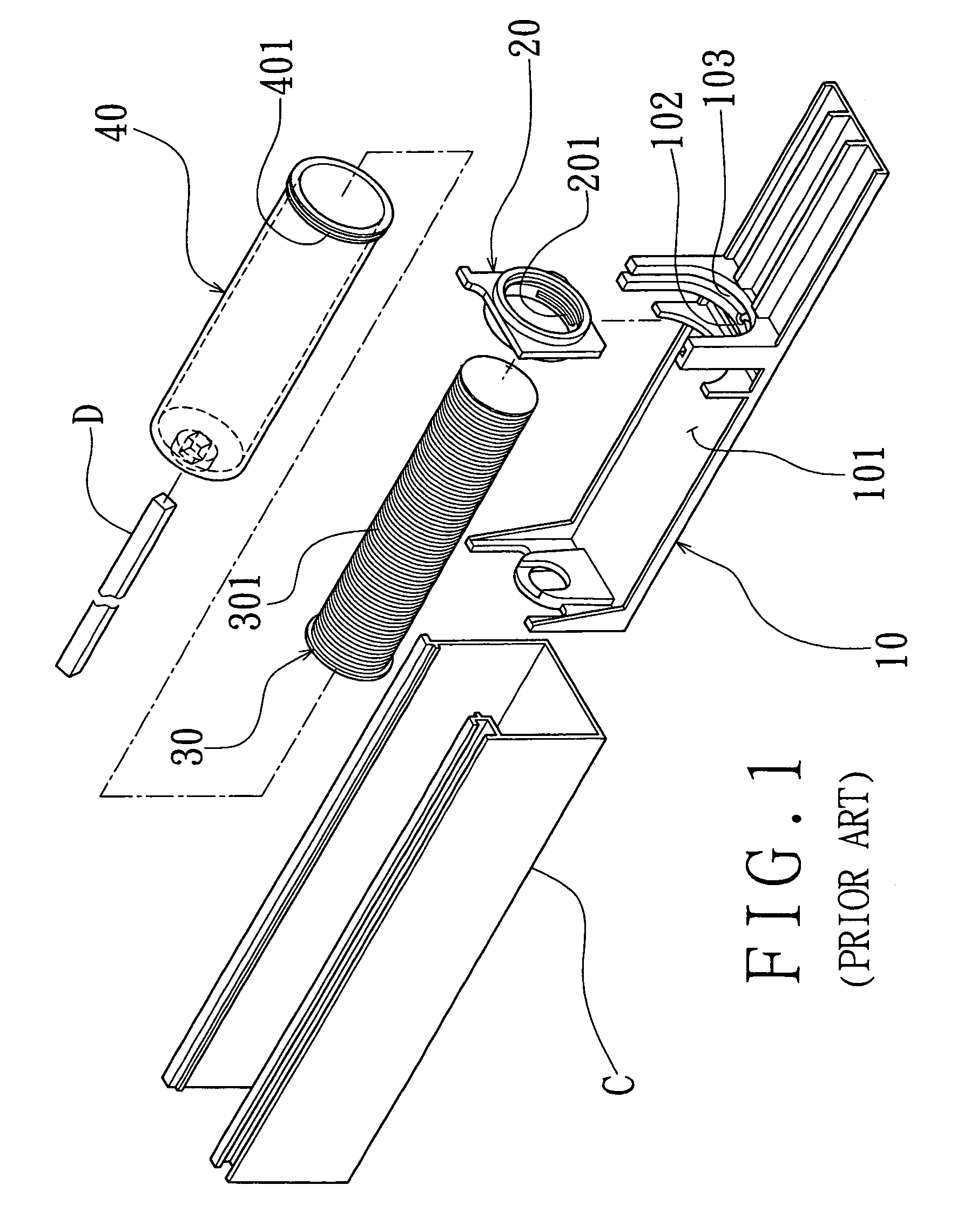
BACKGROUND OF THE INVENTION[0001]1. Field of the Invention[0002]The present invention relates to a tilt and lift device used for adjusting height and tilt angle of a Venetian blind, more particularly one, which can be smoothly operated even if the original tilt cord and lift cord thereof are replaced with thicker tilt cord and lift cord suitable for use with Venetian blinds with large and heavy slats.[0003]2. Brief Description of the Prior Art[0004]Referring to FIGS. 1 and 2, a conventional tilt and lift device of a Venetian blind includes a manual control member (not shown), a supporting base 10, a support 20, a reel tube 30, an external tube 40, and a transmission shaft (D).[0005]The manual control member is secured on an uppermost part of a door (window), and connected to the transmission shaft (D) such that the transmission shaft (D) can be turned in a selected direction by means of operating the manual control member. The supporting base 10 is securely held in a horizontal elon...

Claims


Application Information

Patent Timeline
Patent Type & Authority Patents(United States)
IPC IPC(8): E06B9/303
CPCE06B9/303E06B2009/3227
Inventor LIN, GWO-TSAIR
Owner LIN GWO TSAIR
Learn More