Indexing valve

a technology of indexing valves and valves, applied in the field of control, can solve the problems of valves typically not providing feedback on the flow rate of the gas stream(s) to the operator in any way

Inactive Publication Date: 2007-11-20
CARLISLE FLUID TECH INC
View PDF104 Cites 52 Cited by
  • Summary
  • Abstract
  • Description
  • Claims
  • Application Information

AI Technical Summary

Problems solved by technology

While currently available spray guns typically include valves for adjusting the flow rate(s) of such gas stream(s), such valves typically to not provide feedback on the flow rate(s) of the gas stream(s) to the operator in any way other than by observing the shape of the pattern formed by the atomized coating material particles on an article being coated.

Method used


Image

  • Indexing valve
  • Indexing valve
  • Indexing valve

Examples


Embodiment Construction

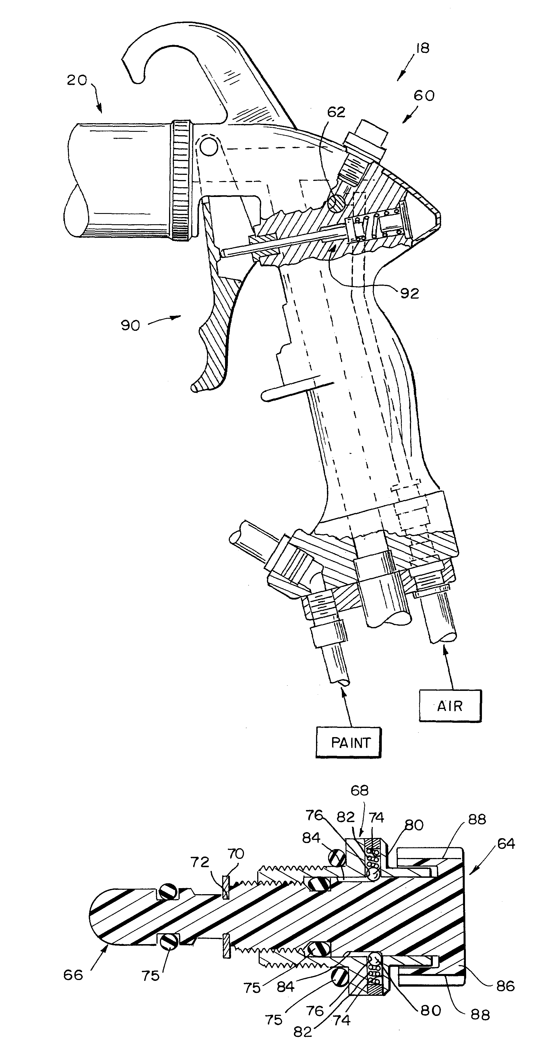
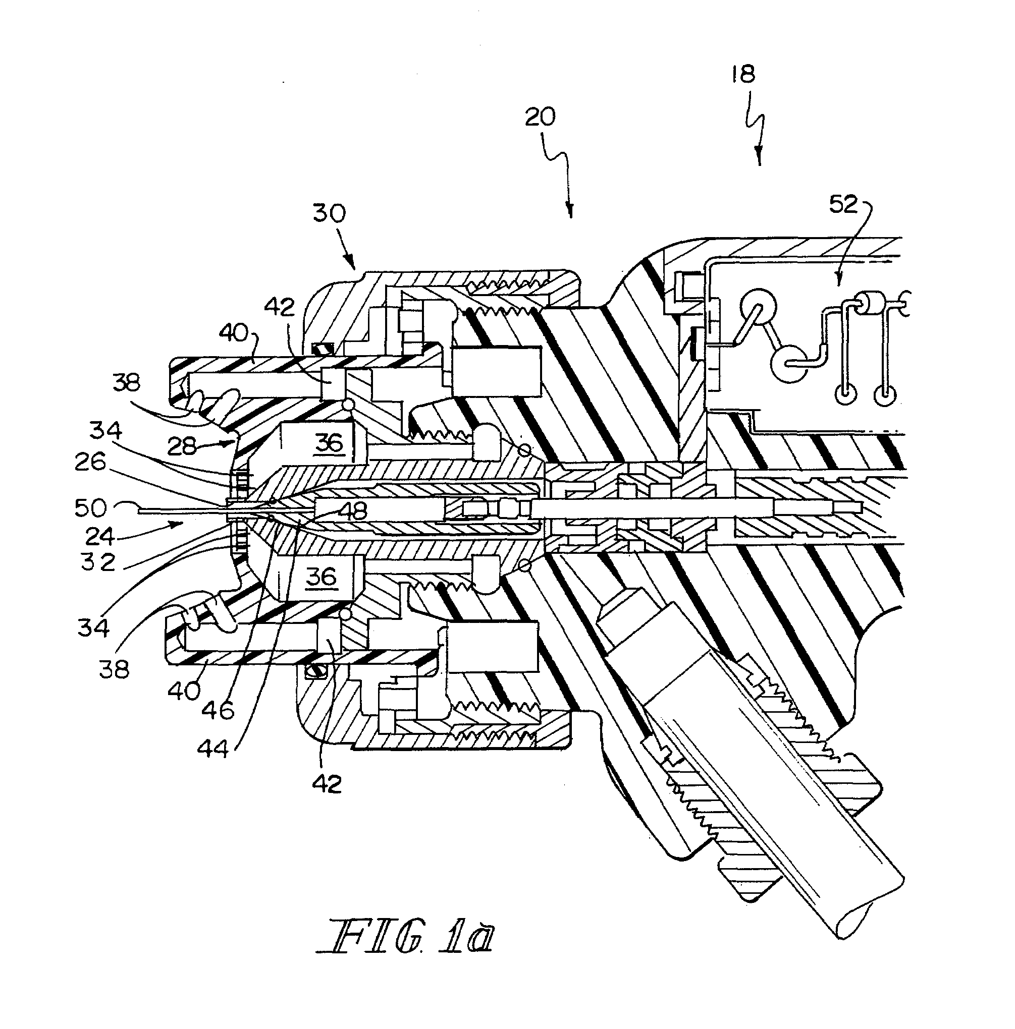
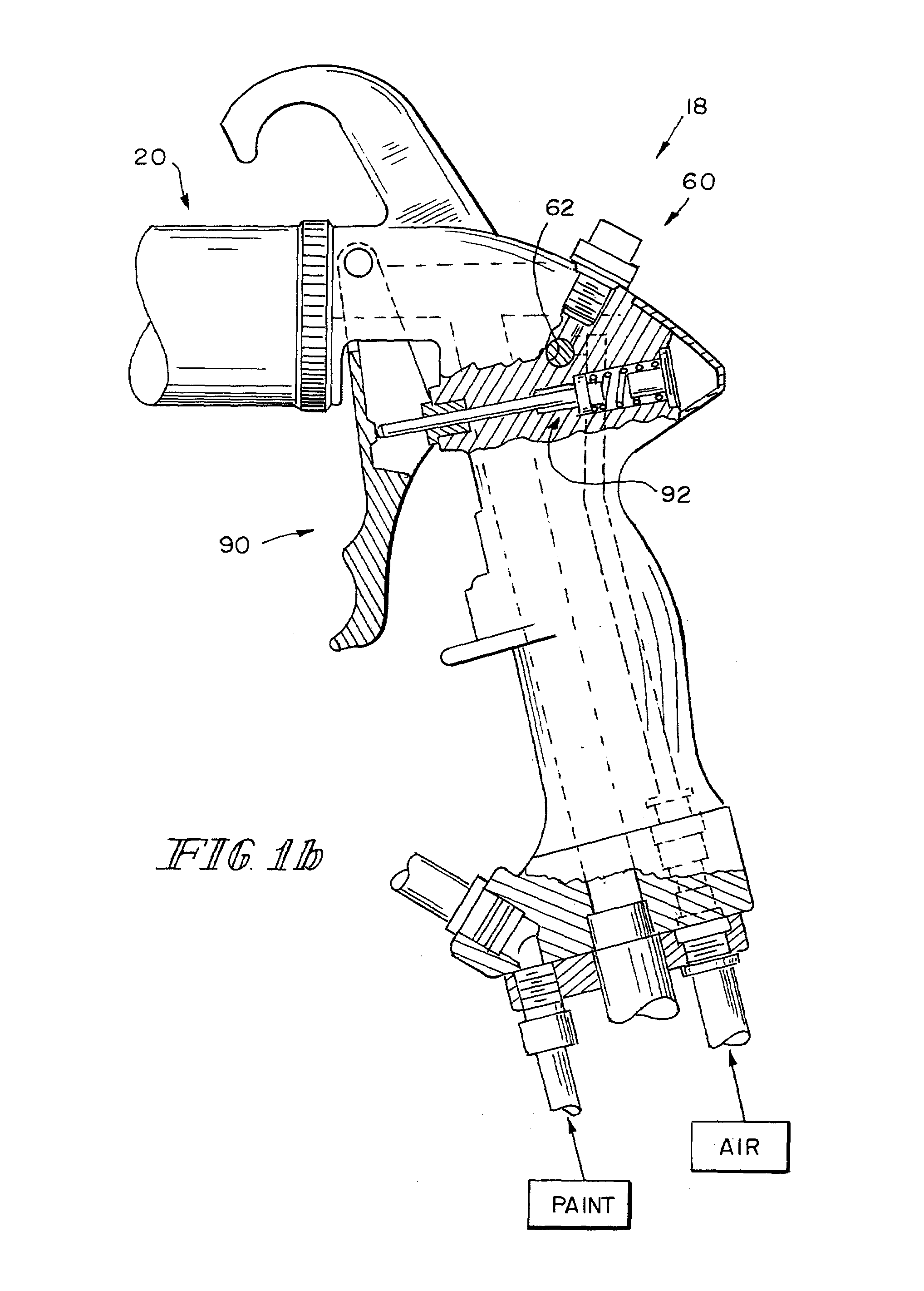
[0025]Referring now to FIGS. 1a-b, a spray gun 18 includes a spray gun body 20 housing a nozzle 24. Nozzle 24 is disposed at the front end of the gun body 20 to dispense fluent coating material (hereinafter sometimes paint) from a front end opening 26. An air cap 28 is attached to the front end of the gun body 20 by a retaining ring 30. The air cap 28 has a central atomizing air orifice 32 and a plurality of atomizing air orifices 34 surrounding the central orifice 32. These orifices communicate with a gallery 36 which is coupled to a supply of compressed air. Shaping air orifices 38 are provided on air horns 40 which extend forward from diametrically opposite sides of the air cap 28. The shaping air orifices 38 communicate with a shaping air supply gallery 42 which is also coupled to a supply of compressed air. Shaping air orifices 38 provide air for shaping a spray pattern of paint flowing from the nozzle 24 and atomized by air from atomizing air orifices 32, 34.

[0026]The spray gu...


PUM


Abstract

A valve for controlling the flow of a gas or mixture of gases through a passageway in a coating material dispensing device includes first and second valve portions. The first valve portion is adjustable with respect to the second valve portion selectively to adjust the flow through the passageway. One of the first and second valve portions includes a first engagement member and the other of the first and second valve portions includes a second engagement member. Engagement of the first and second engagement members indicates the relative orientation of the first and second valve portions.

Description

FIELD OF THE INVENTION[0001]This invention relates to controls for coating dispensing devices (hereinafter sometimes spray guns). It is disclosed in the context of a valve for controlling the flow of shaping air to the air cap of a spray gun. However, it is believed to be useful in other applications as well.BACKGROUND OF THE INVENTION[0002]Various types of manual and automatic spray guns are known. There are, for example, the manual spray guns illustrated and described in the following listed U.S. patents and published applications: 2003 / 0006322; U.S. Pat. Nos. 6,712,292; 6,698,670; 6,669,112; 6,572,029; 6,460,787; 6,402,058; U.S. Pat. No. RE36,378; 6,276,616; 6,189,809; 6,179,223; 5,836,517; 5,829,679; 5,803,313; U.S. Pat. No. RE35,769; 5,639,027; 5,618,001; 5,582,350; 5,553,788; 5,400,971; 5,395,054; D349,559; 5,351,887; 5,332,159; 5,332,156; 5,330,108; 5,303,865; 5,299,740; 5,289,974; 5,284,301; 5,284,299; 5,236,129; 5,209,405; 5,209,365; 5,178,330; 5,119,992; 5,118,080; 5,180,1...

Claims


Application Information

Patent Timeline
Patent Type & Authority Patents(United States)
IPC IPC(8): B05B1/28
CPCB05B7/0815F16K35/04B05B7/12F16K1/04
Inventor ALEXANDER, KEVIN L.RODGERS, MICHAEL C.
Owner CARLISLE FLUID TECH INC
Why Eureka
Try Eureka