Method and apparatus for capturing images using a color laser projection display

a color laser and projection display technology, applied in the field of electronic displays, can solve the problems of lack of durability, high cost, limited flexibility,

Active Publication Date: 2007-11-27
MICROVISION
View PDF8 Cites 103 Cited by
  • Summary
  • Abstract
  • Description
  • Claims
  • Application Information

AI Technical Summary

Problems solved by technology

Electronic cameras have historically suffered from a number of shortcomings, including high cost, lack of durability, size, weight, limited flexibility and the like.
These flash units are typically heavy consumers of battery power, which tends to shorten the battery life of the camera and render it less useful.
Moreover, it is often necessary for a photographer to wait for the battery to charge the flash unit before taking each picture.
Further, the use of a flash unit produces numerous undesirable side effects, including reflections that distort and mar the photograph.
These screens add to the overall cost of the camera, are often difficult to view in direct sunlight and are prone to damage and failure.

Method used


Image

  • Method and apparatus for capturing images using a color laser projection display
  • Method and apparatus for capturing images using a color laser projection display
  • Method and apparatus for capturing images using a color laser projection display

Examples


Embodiment Construction

[0015]Illustrative embodiments of the invention are described below. In the interest of clarity, not all features of an actual implementation are described in this specification. It will of course be appreciated that in the development of any such actual embodiment, numerous implementation-specific decisions must be made to achieve the developers' specific goals, such as compliance with system-related and business-related constraints, which will vary from one implementation to another. Moreover, it will be appreciated that such a development effort might be complex and time-consuming, but would nevertheless be a routine undertaking for those of ordinary skill in the art having the benefit of this disclosure.

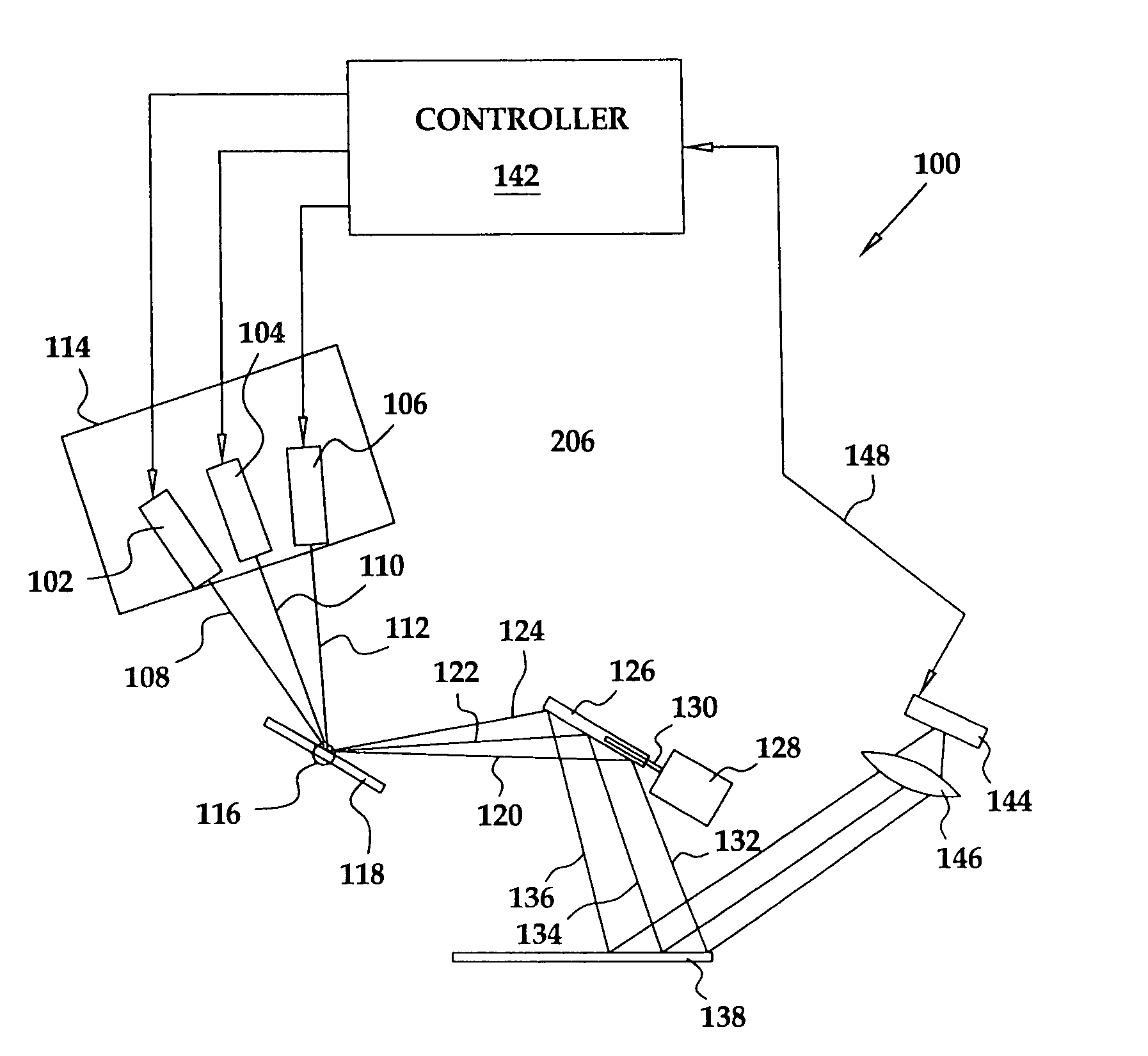
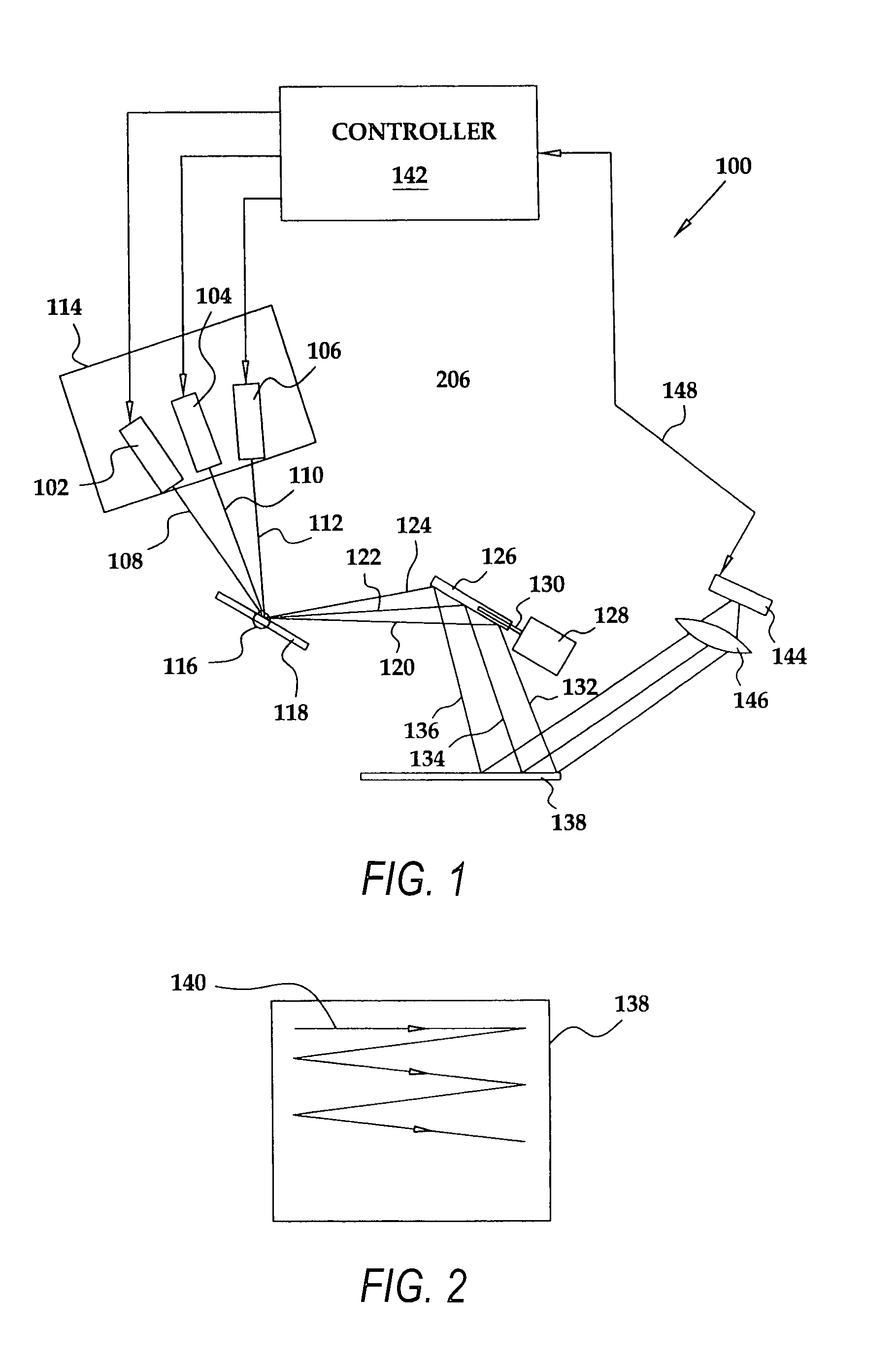
[0016]Turning now to the drawings, and specifically referring to FIG. 1, a stylistic block diagram of a laser projection display (LPD) 100, in accordance with one embodiment of the present invention, is shown. In the illustrated embodiment, the LPD 100 includes three lasers 102, ...


PUM


Abstract

A method and apparatus are provided to capture images using a laser projection display (LPD). In a full color LPD camera, three lasers (red, blue, and green) are deployed to scan an image and receive reflected laser light therefrom. The reflected laser light may be analyzed and assembled into a picture. The LPD may also be used to display the picture, to operate as a viewfinder, to print the picture, to operate as a range finder, and the like.

Description

CROSS REFERENCE TO RELATED APPLICATION[0001]This application claims the priority benefit of U.S. Provisional Application Ser. No. 60 / 534,005, filed Dec. 31, 2003.BACKGROUND OF THE INVENTION[0002]1. Field of the Invention[0003]This invention relates generally to electronic displays, and, more particularly, to a laser projection display and its use as an image capture device.[0004]2. Description of the Related Art[0005]Electronic cameras have historically suffered from a number of shortcomings, including high cost, lack of durability, size, weight, limited flexibility and the like. Further, conventional cameras have typically relied upon a flash unit to provide adequate illumination. These flash units are typically heavy consumers of battery power, which tends to shorten the battery life of the camera and render it less useful. Moreover, it is often necessary for a photographer to wait for the battery to charge the flash unit before taking each picture. Further, the use of a flash uni...

Claims


Application Information

Patent Timeline
Patent Type & Authority Patents(United States)
IPC IPC(8): G03B15/02G03B29/00G01S7/481G01S17/89H04N9/31
CPCG01S7/4811H04N9/3129G01S17/89G01S7/4817
Inventor TAN, CHINHDVORKIS, PAULGOLDMAN, RONNAMBUDIRI, NARAYANWITTENBERG, CARLSTERN, MIKLOSYAVID, DMITRIYWOOD, FREDERICK F.
Owner MICROVISION
Why Eureka
Try Eureka