Linear oscillating actuator

a linear actuator and actuator technology, applied in the direction of mechanical vibration separation, dynamo-electric machines, mechanical energy handling, etc., can solve the problems of undue stress on the leaf spring, and the above actuator is found to be unsatisfactory in absorbing incidental vibrations associated with such displacement, so as to achieve the effect of minimal incidental vibration or stress and minimal fatigu

Active Publication Date: 2007-12-04
MATSUSHITA ELECTRIC WORKS LTD
View PDF13 Cites 19 Cited by
  • Summary
  • Abstract
  • Description
  • Claims
  • Application Information

AI Technical Summary

Benefits of technology

[0003]In view of the above problem, the present invention has been accomplished to provide a linear oscillating actuator which is capable of giving a smooth reciprocator movement with a minimum of incidental vibrations or stresses. The actuator in accordance with the present invention includes an oscillator carrying a permanent magnet as well as an output shaft which is adapted to be connected to drive a load, and a stator assembly carrying an electromagnet. The electromagnet generates a magnetic field which interacts with the permanent magnet to reciprocate the oscillator relative to the stator assembly in a linear path. A spring link is provided to resiliently support the oscillator to the stator assembly with a gap distance left therebetween for allowing the oscillator to reciprocate in the linear path. The spring link is configured to deform resiliently also in a direction other than along the linear path so as to allow the oscillator to move to and away from the stator assembly or to twist relative to the stator assembly about a gap axis running along the gap distance. Thus, the spring link can absorb incidental stresses or displacements from which the oscillator may suffer in the directions other than along the linear path, assuring to give a smooth reciprocatory movement to the oscillator with a minimum of fatigue accumulated in the spring link.
[0004]This is particularly advantageous when the oscillator is lifted above the stator assembly by means of the spring link. For instance, when the two spring links are provided to connect opposite ends of the oscillator respectively to the stator assembly, the two spring links project upwardly from the stator assembly to lift the oscillator above the stator assembly. In this case, the spring link is susceptible to a compressive or torsional force from the oscillator accompanied with the linear reciprocatory movement, and can absorb such incident stresses for smooth reciprocatory movement.
[0007]The spring link may be molded together with a molded part of the oscillator for reducing the number of components.
[0008]In case a parallel pair of oscillators are supported commonly to the stator assembly to reciprocate in a reverse phase relation with each other, the oscillators are interconnected to each other by means of a coupler spring for assisting the reverse phase relation. The coupler spring is resiliently deformed along the linear path as well as the gap varying direction for giving the function of absorbing the incidental stresses also by the coupler spring. In this version, the spring link and the coupler spring may be integrally molded together with a molded part of the oscillator for minimizing the number of components.

Problems solved by technology

In view of that the linear movement of the oscillator may sometimes accompany minor displacements in the directions other than along the linear path, the leaf spring are likely to suffer from undue stresses resulting from the displacements.
In this sense, the above actuator is found not satisfactory to absorb incidental vibrations associated with such displacements.

Method used


Image

  • Linear oscillating actuator
  • Linear oscillating actuator
  • Linear oscillating actuator

Examples


Embodiment Construction

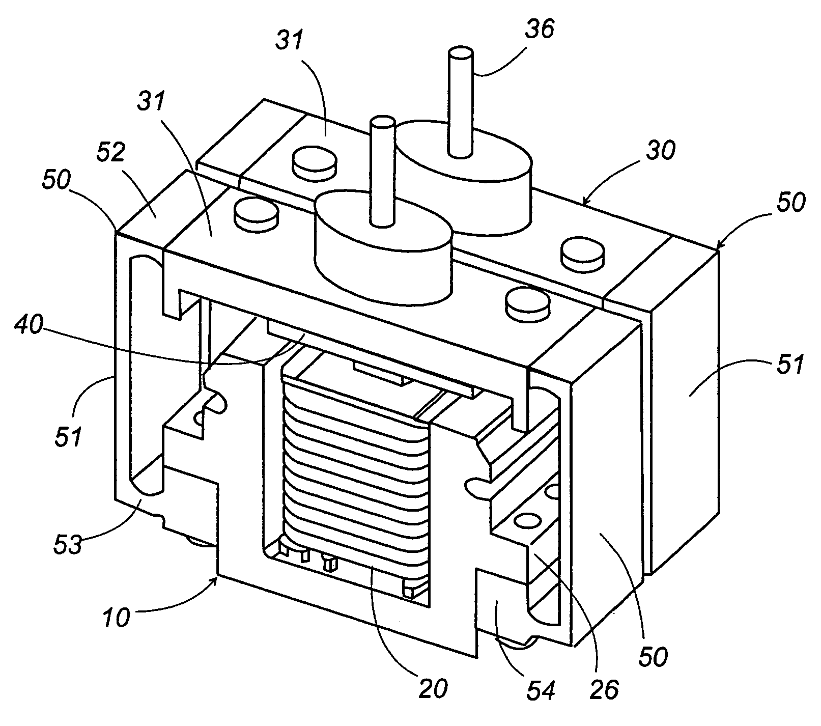
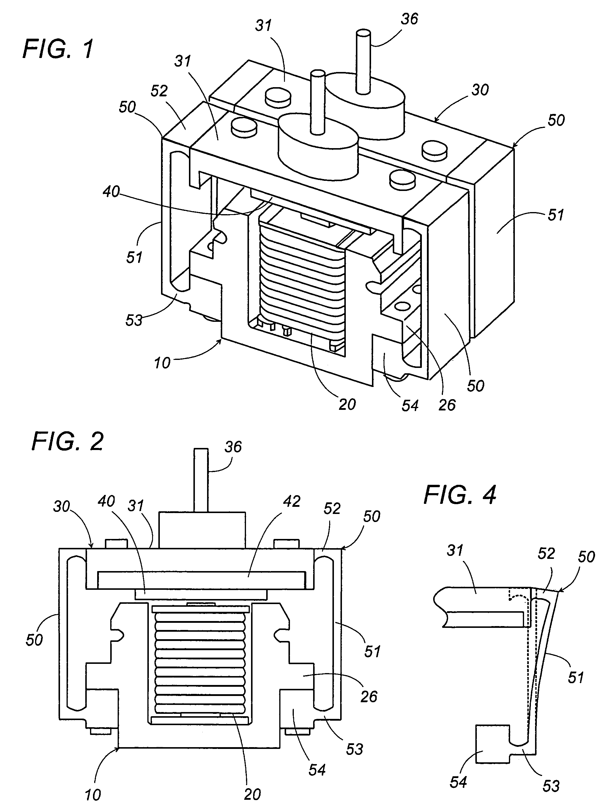
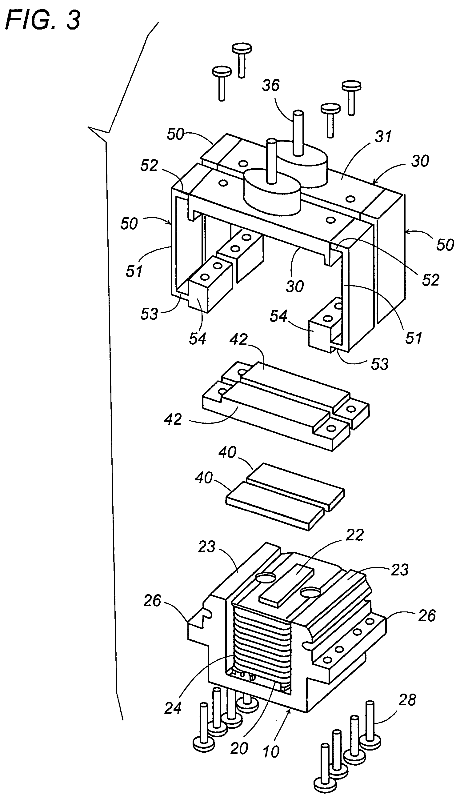
[0019]Referring now to FIGS. 1 to 3, there is shown a linear oscillating actuator in accordance with a preferred embodiment of the present invention. The actuator includes two oscillators 30 commonly supported to a single stator assembly 10 to reciprocate in a reverse phase relation with each other, although the present invention is not limited thereto and may includes a single or more than two oscillators common to the one stator assembly 10.

[0020]The stator assembly 10 carries an electromagnet 20, while each oscillator 30 carries a permanent magnet 40 as well as an output shaft 36 for connection to a load to be driven to reciprocate in a linear path. For instance, the actuator may be incorporated in a dry shaver to reciprocate inner cutters relative to an outer cutter. The electromagnet 20 includes an E-shaped stator having a center core 22 and a pair of side cores 23. A coil 24 is wound around the center core 22 to magnetize pole ends at the respective upper ends of the center an...


PUM


Abstract

A linear oscillating actuator gives a smooth reciprocatory movement with a minimum of incidental vibrations or stresses. The actuator includes an oscillator carrying a permanent magnet as well as an output shaft which is adapted to be connected to drive a load, and a stator assembly carrying an electromagnet. The electromagnet generates a magnetic field which interacts with the permanent magnet to reciprocate the oscillator relative to the stator assembly in a linear path. A spring link is provided to resiliently support the oscillator to the stator assembly with a gap distance left therebetween for allowing the oscillator to reciprocate in the linear path. The spring link is configured to deform resiliently also in a direction other than along the linear path so as to allow the oscillator to move to and away from the stator assembly or to twist relative to the stator assembly. Thus, the spring link can absorb incidental stresses or displacements from which the oscillator may suffer in the directions other than along the linear path, assuring to give a smooth reciprocatory movement to the oscillator with a minimum of fatigue accumulated in the spring link.

Description

TECHNICAL FIELD[0001]The present invention is directed to a linear oscillating actuator with an oscillator movably supported to a stator assembly by means of a spring link.BACKGROUND ART[0002]EP 0 674 979 A discloses a linear oscillating actuator utilized for driving inner cutters of a dry shaver. The actuator is composed of a stator assembly carrying an electromagnet, and an oscillator carrying a permanent magnet. The oscillator is movably supported to reciprocate in a linear path relative to the stator assembly by an interaction with the electromagnet and the permanent magnet. The stator assembly includes a stator core and a frame which projects on top of the stator core for suspending the oscillator upwardly of the stator core with a magnetic gap therebetween. In order to suspend and also to movably support the oscillator, leaf springs are utilized to connect the oscillator to the frame. Although the leaf springs are sufficiently resilient to allow the movement of the oscillator ...

Claims


Application Information

Patent Timeline
Patent Type & Authority Patents(United States)
IPC IPC(8): H02K33/00H02K33/16H02K33/02H02K33/18H02K41/00
CPCH02K33/16H02K7/065H02K15/14H02K33/02H02K15/03H02K3/48B06B1/045
Inventor SANEMATSU, WATARUNAKAYAMA, SATOSHIFUJIWARA, MAKOTOMISHIMA, CHIZUKOISHIGAMI, YOUHEI
Owner MATSUSHITA ELECTRIC WORKS LTD
Why Eureka
Try Eureka