Contactless card reader integrated into a touchpad

a touchpad and card reader technology, applied in instruments, sensing record carriers, computing, etc., can solve problems such as real-time detection

Active Publication Date: 2007-12-11
CIRQUE CORPORATION
View PDF4 Cites 60 Cited by
  • Summary
  • Abstract
  • Description
  • Claims
  • Application Information

AI Technical Summary

Benefits of technology

[0011]It is an object of the present invention to provide a system that integrates a contactless smart card reader in an electronic appliance that is already widely available.

Problems solved by technology

Despite the obvious advantages that can be provided by smart cards they have never really caught on in the United States.

Method used


Image

  • Contactless card reader integrated into a touchpad
  • Contactless card reader integrated into a touchpad
  • Contactless card reader integrated into a touchpad

Examples


Embodiment Construction

[0020]Reference will now be made to the drawings in which the various elements of the present invention will be given numerical designations and in which the invention will be discussed so as to enable one skilled in the art to make and use the invention. It is to be understood that the following description is only exemplary of the principles of the present invention, and should not be viewed as narrowing the claims which follow.

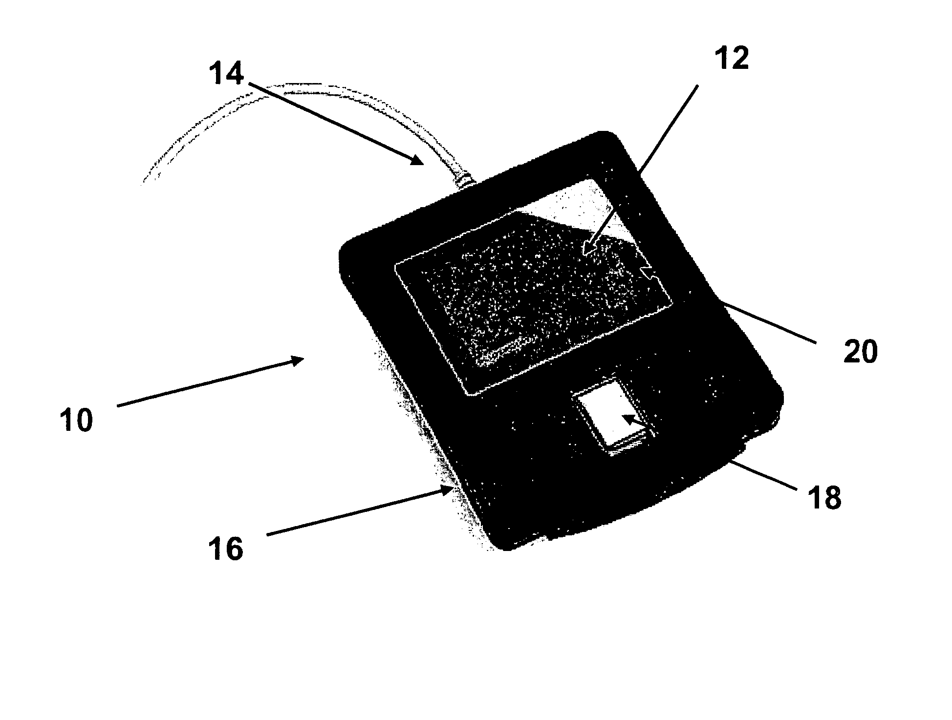
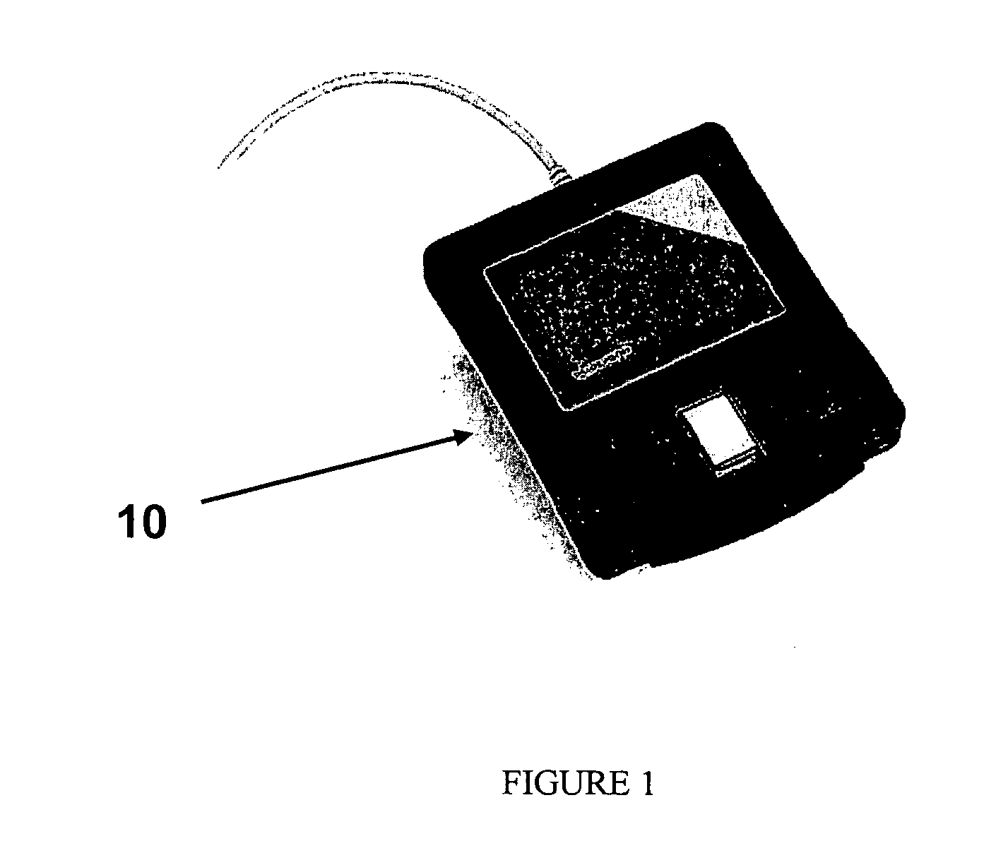
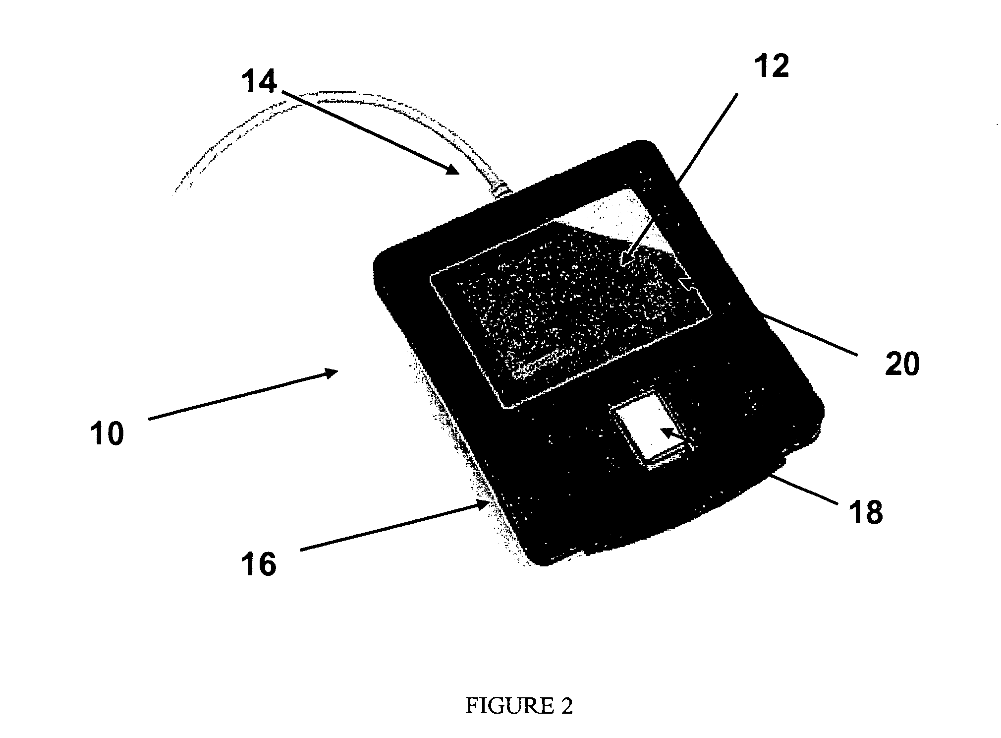
[0021]The presently preferred embodiment of the invention is a touchpad, such as a touchpad sold by CIRQUE® Corporation and shown in FIG. 1. The CIRQUE® GLIDEPOINT® touchpad is installed in many electronic appliances and as a stand-alone device. FIG. 1 is an illustration of a stand-alone touchpad 10. Such electronic appliances that incorporate a touchpad include many portable electronic appliances such as laptop computers, personal digital assistants (PDAs), mobile telephones, digital cameras, digital camcorders, etc.

[0022]The CIRQUE® GLIDEPOINT® technology...


PUM


Abstract

A contactless smart card reader that is integrated into the hardware of a touchpad, wherein the circuit board substrate of the touchpad provides a mechanical substrate on which the hardware of the contactless smart card reader can be disposed, and wherein the touchpad is already widely distributed in other electronic appliances, and as a stand-alone device.

Description

BACKGROUND OF THE INVENTION[0001]1. Field of the Invention[0002]This invention relates generally to contactless smart cards and touchpads. More specifically, the present invention enables combining a contactless smart card reader and the hardware of a capacitance-sensitive touchpad to thereby offer the mechanical characteristics of the touchpad to the mechanical requirements of the contactless smart card reader.[0003]2. Description of Related Art[0004]The state of the art of smart cards has changed as the concept of smart cards has evolved. A typical smart card is a device having a housing that is often the same size as a credit card. The housing typically includes some sort of memory that enables the smart card to store information. Thus, the smart card is “smart” enough to hold its own data and applications. Some smart cards also include some rudimentary data processing capabilities through the addition of a processor. The result is that it is possible for the smart card to carry ...

Claims


Application Information

Patent Timeline
Patent Type & Authority Patents(United States)
IPC IPC(8): G06K5/00
CPCG06F3/03547G06K7/08G06K7/00G06K17/00
Inventor MOORE, J. DOUGLAS
Owner CIRQUE CORPORATION
Why Eureka
Try Eureka