Status indicator

a technology of status indicators and current sensors, which is applied in the direction of testing circuits, instruments, sustainable buildings, etc., can solve the problem that the information provided by current sensors is insufficient to determine whether the load is malfunctioning or no

Active Publication Date: 2007-12-18
VERIS INDS
View PDF41 Cites 33 Cited by
  • Summary
  • Abstract
  • Description
  • Claims
  • Application Information

AI Technical Summary

Problems solved by technology

Many industrial, commercial and residential environments incorporate electrical loads that are widely distributed geographically and often sited in difficult to access locations.
While the output of a current sensor, such as the internal sensor of the remote control and status monitoring device 10, can be used to indicate whether current is flowing to a remote load, the information provide by a current sensor is insufficient to determine whether the load is malfunctioning because there is no information indicating whether the load circuit is closed and, therefore, current flow to the load should be expected.

Method used


Image

  • Status indicator
  • Status indicator
  • Status indicator

Examples


Embodiment Construction

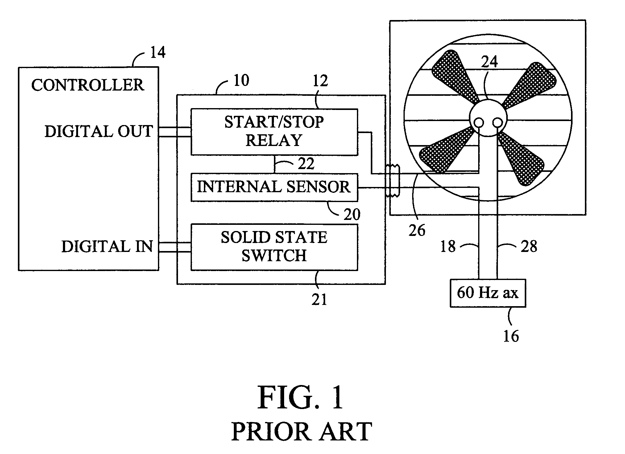
[0012]In many environments electrical loads that are widely distributed geographically are controlled and monitored from a central location. FIG. 1 illustrates a circuit and a device enabling controlling and monitoring the operation of a remote load 24 from a central controller 14. A remote control and status monitoring device 10 includes a start / stop relay 12 that is energized or otherwise controlled by digital output from the controller 14. Power from a power source 16, such as a utility transmission line, is provided by a wire 18 which is interconnected to the start / stop relay 12 of the device 10. The start / stop relay 12 is likewise interconnected to an internal sensor, namely, a current transformer 20 by a wire 22. The output of the internal sensor 20 is interconnected to a load 24 by a wire 26. The load 24 is interconnected to the source 16 by a wire 52. Accordingly, a loop for current flow is provided by wire 18, the start / stop relay 12, the wire 22, the internal sensor 20, th...


PUM


Abstract

A status indicator indicates an operating state, including an electrical malfunction, of an electrical load that is located and controlled from locations remote from a monitoring location.

Description

CROSS REFERENCE TO RELATED DOCUMENTS[0001]The present application claims the benefit of U.S. Provisional Application No. 60 / 611,967, filed Sep. 21, 2004.CROSS-REFERENCE TO RELATED APPLICATIONS[0002]Not applicable.STATEMENT REGARDING FEDERALLY SPONSORED RESEARCH OR DEVELOPMENT[0003]Not applicable.BACKGROUND OF THE INVENTION[0004]The present invention relates to a device for indicating the operating state of an electrical load and, more particularly, to a device for indicating an operating state of a load located and controlled at locations remote to a monitoring location.[0005]Many industrial, commercial and residential environments incorporate electrical loads that are widely distributed geographically and often sited in difficult to access locations. However, the operation of these loads, for example, small fan motors or lights can be important to maintaining a safe environment or the successful completion of a process that may involve costly or hazardous equipment or materials and...

Claims


Application Information

Patent Timeline
Patent Type & Authority Patents(United States)
IPC IPC(8): G08B21/00G01R15/18G01R31/08G01R31/14H02H3/00
CPCG01R31/343Y02B90/20
Inventor BOWMAN, MARC
Owner VERIS INDS
Why Eureka
Try Eureka